Toyota Tacoma (2015-2018) Service Manual: Unable to Unlock Steering Wheel (Engine cannot Start)
DESCRIPTION
The steering lock actuator assembly activates the steering lock motor and moves the lock bar into the steering column to lock the steering.
The steering may not unlock when the lock bar gets stuck in the lock hole of the steering column. In this case, if the engine switch is turned on (IG) while shaking the steering wheel, as is done for a vehicle with a mechanical key, the lock bar will be unlocked. If the certification ECU (smart key ECU assembly) or ECM is replaced, the system needs to be initialized. Otherwise, the steering cannot be unlocked and the engine cannot be started.
Related Data List and Active Test Items|
Problem Symptom |
Data List Item |
Active Test Item |
|---|---|---|
|
Unable to unlock steering wheel (Engine cannot start) |
Smart Key
|
- |
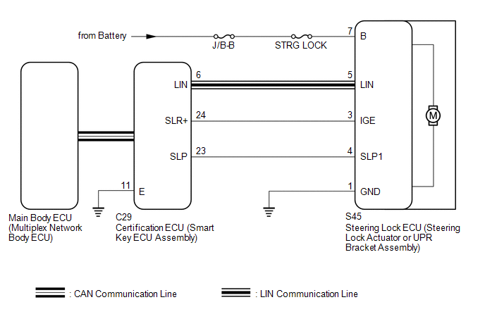
WIRING DIAGRAM
CAUTION / NOTICE / HINT
NOTICE:
- When using the Techstream with the engine switch off, connect the Techstream to the vehicle and turn a courtesy light switch on and off at intervals of 1.5 seconds or less until communication between the Techstream and the vehicle begins. Then select the vehicle type under manual mode and enter the following menus: Body Electrical / Smart Key. While using the Techstream, periodically turn a courtesy light switch on and off at intervals of 1.5 seconds or less to maintain communication between the Techstream and the vehicle.
- Perform either of the following operations to lock/unlock the steering:
- To unlock the steering, carry the key and turn the engine switch on (ACC) or on (IG).
- To lock the steering, turn the engine switch off with the shift lever in P, and then open a door.
- The steering lock system uses LIN communication. First perform the inspections
in "How to Proceed with Troubleshooting" to confirm that there are no communication
malfunctions before proceeding with troubleshooting (See page
.gif) ).
). - After performing repairs, confirm that the problem does not recur.
- Make sure that no DTCs are output. If any DTCs are output, proceed to
the Diagnostic Trouble Code Chart (See page
).
- Inspect the fuses for circuits related to this system before performing the following procedure.
- When replacing the steering lock ECU (steering lock actuator or UPR
bracket assembly) or certification ECU (smart key ECU assembly), registration
must be performed (See page ).
- When disconnecting the cable from the negative (-) battery terminal,
some systems need to be initialized after the cable is reconnected (See
page ).
- If the steering lock ECU (steering lock actuator or UPR bracket assembly) is replaced, be sure to confirm that the steering is unlocked by turning the steering wheel to the left and right before starting the engine. This function prevents the engine from starting while the steering is locked. If the steering is locked for any reason, open and close a door with the engine switch off, and then unlock the steering by pressing the engine switch.
PROCEDURE
|
1. |
CHECK ENGINE SWITCH (SWITCH CONDITION) |
(a) Check the power source mode change.
(1) When the key is inside the vehicle and the shift lever is in P, check that pressing the engine switch with the brake pedal released causes the power source mode to change as follows:
OK:
Off → On (ACC) → On (IG) → Off
| NG | .gif) |
GO TO ENTRY AND START SYSTEM (for Start Function) (PROBLEM SYMPTOMS TABLE) |
|
.gif)
|
2. |
CHECK INDICATOR |
(a) With the engine switch on (IG), check that Steering Lock active is displayed on the multi-information display in the combination meter assembly.
Result|
Result |
Proceed to |
|---|---|
|
Steering Lock active is displayed. |
A |
|
Steering Lock active are not displayed. |
B |
| B | |
GO TO STEP 4 |
|
|
3. |
CHECK STEERING LOCK |
(a) Turn the steering wheel left and right, and then press the engine switch.
(b) Check that the steering is unlocked.
Result|
Result |
Proceed to |
|---|---|
|
The steering is unlocked. |
A |
|
The steering is not unlocked. |
B |
| A | |
END |
|
|
4. |
CHECK FOR DTC |
(a) Using the Techstream, check if the certification ECU (smart key ECU assembly)
DTC is output (See page ).
|
Result |
Proceed to |
|---|---|
|
DTCs are not output. |
A |
|
DTCs are output. |
B |
| B | |
GO TO DIAGNOSTIC PROCEDURE INDICATED BY OUTPUT DTC |
|
|
5. |
READ VALUE USING TECHSTREAM (UNLOCK REQUEST RECEIVE) |
(a) Use the Data List to check if the steering lock request is functioning properly.
Smart Key|
Tester Display |
Measurement Item/Range |
Normal Condition |
Diagnostic Note |
|---|---|---|---|
|
Unlock Request Receive |
Reception state of steering unlock request signal by certification ECU (smart key ECU assembly) / OK or NG HINT:
|
OK: Within 10 seconds of turning engine switch on (IG) or on (ACC) or starting engine NG: Except above |
|
OK:
Within 10 seconds of turning the engine switch on (ACC) or on (IG) or starting the engine, the Data List item changes to "OK".
| NG | |
GO TO STEP 12 |
|
|
6. |
READ VALUE USING TECHSTREAM (L CODE CHECK) |
(a) Use the Data List to check if L code certification is functioning properly.
Smart Key|
Tester Display |
Measurement Item/Range |
Normal Condition |
Diagnostic Note |
|---|---|---|---|
|
L Code Check |
Verification result between certification ECU (smart key ECU assembly) and steering lock ECU (steering lock actuator or UPR bracket assembly) / OK or NG |
OK: Verification result normal NG: Verification result abnormal |
When a malfunction is present:
|
OK:
OK is displayed on the Techstream.
HINT:
Reasons for verification failure:
- The steering lock ECU (steering lock actuator or UPR bracket assembly) or certification ECU (smart key ECU assembly) is malfunctioning.
- There is a problem with the communication between ECUs.
- An ECU is replaced, but is not registered.
- An ECU is replaced with an ECU which has a code already stored in it.
| NG | |
GO TO STEP 11 |
|
|
7. |
INSPECT STEERING LOCK ECU (STEERING LOCK ACTUATOR OR UPR BRACKET ASSEMBLY) |
|
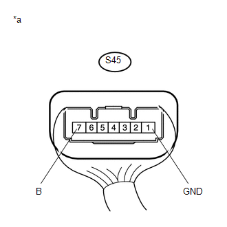
(a) Measure the resistance and voltage according to the value(s) in the table below. Standard Resistance:
NOTICE: If the result is not as specified, check for looseness in the ground cable connection. Standard Voltage:
|
|
| NG | |
REPAIR OR REPLACE HARNESS OR CONNECTOR |
|
|
8. |
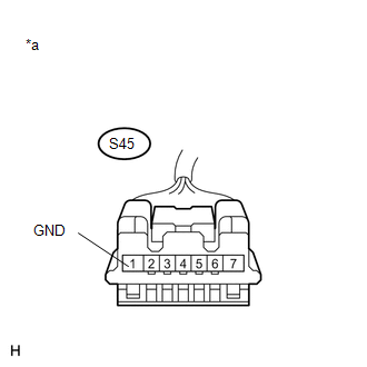
CHECK HARNESS AND CONNECTOR (GROUND) |
(a) Disconnect the steering lock ECU (steering lock actuator or UPR bracket assembly) connector.
|
(b) Measure the resistance according to the value(s) in the table below. Standard Resistance:
|
|
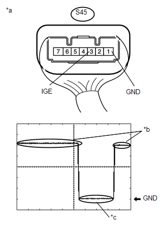
(c) Reconnect the steering lock ECU (steering lock actuator or UPR bracket assembly) connector.
|
(d) Check the signal waveform according to the condition(s) in the table below. Standard Frequency:
HINT:
|
|
| OK | |
REPLACE STEERING LOCK ECU (STEERING LOCK ACTUATOR OR UPR BRACKET ASSEMBLY) |
|
|
9. |
CHECK HARNESS AND CONNECTOR (STEERING LOCK ECU (STEERING LOCK ACTUATOR OR UPR BRACKET ASSEMBLY) - CERTIFICATION ECU (SMART KEY ECU ASSEMBLY)) |
(a) Make sure that there is no looseness at the locking part and the connecting part of the connectors.
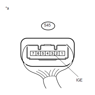
(b) Disconnect the S45 steering lock ECU (steering lock actuator or UPR bracket assembly) connector.
(c) Disconnect the C29 certification ECU (smart key ECU assembly) connector.
(d) Check for deformation and corrosion of the connector case and terminals.
OK:
There is no deformation or corrosion of the connector case or terminals.
(e) Measure the resistance according to the value(s) in the table below.
Standard Resistance:
|
Tester Connection |
Condition |
Specified Condition |
|---|---|---|
|
S45-3 (IGE) - C29-24 (SLR+) |
Always |
Below 1 Ω |
|
S45-3 (IGE) or C29-24 (SLR+) - Body ground |
Always |
10 kΩ or higher |
| NG | |
REPAIR OR REPLACE HARNESS OR CONNECTOR |
|
|
10. |
INSPECT STEERING LOCK ECU (STEERING LOCK ACTUATOR OR UPR BRACKET ASSEMBLY) |
(a) Reconnect the steering lock ECU (steering lock actuator or UPR bracket assembly) connector.
(b) Reconnect the C29 certification ECU (smart key ECU assembly) connector.
|
(c) Measure the voltage according to the value(s) in the table below. Standard Voltage:
|
|
| OK | |
REPLACE CERTIFICATION ECU (SMART KEY ECU ASSEMBLY) |
| NG | |
REPLACE STEERING LOCK ECU (STEERING LOCK ACTUATOR OR UPR BRACKET ASSEMBLY) |
|
11. |
REPLACE STEERING LOCK ECU (STEERING LOCK ACTUATOR OR UPR BRACKET ASSEMBLY) |
(a) Replace the steering lock ECU (steering lock actuator or UPR bracket assembly)
with a new one (See page ).
(b) Perform registration (See page ).
(c) Turn the engine switch on (IG).
(d) Use the Data List to check if L code certification is functioning properly again.
Smart Key|
Tester Display |
Measurement Item/Range |
Normal Condition |
Diagnostic Note |
|---|---|---|---|
|
L Code Check |
Verification result between certification ECU (smart key ECU assembly) and steering lock ECU (steering lock actuator or UPR bracket assembly) / OK or NG |
OK: Verification result normal NG: Verification result abnormal |
When a malfunction is present:
|
OK:
OK is displayed on the Techstream.
| OK | |
END |
| NG | |
REPLACE CERTIFICATION ECU (SMART KEY ECU ASSEMBLY) |
|
12. |
INSPECT STEERING LOCK ECU (STEERING LOCK ACTUATOR OR UPR BRACKET ASSEMBLY) |
|
(a) Measure the voltage according to the value(s) in the table below. Standard Voltage:
|
|

| NG | |
GO TO STEP 15 |
|
|
13. |
READ VALUE USING TECHSTREAM (STEERING UNLOCK) |
(a) Check that the steering is locked.
(b) Read the Data List according to the display on the Techstream.
Smart Key|
Tester Display |
Measurement Item/Range |
Normal Condition |
Diagnostic Note |
|---|---|---|---|
|
Steering Unlock |
State of whether steering lock ECU (steering lock actuator or UPR bracket assembly) determined steering is unlocked / Set or Unset |
Set: Steering unlocked Unset: Steering locked |
If this item displays "Unset", the steering does not unlock (engine cannot be started). |
OK:
Set is displayed on the Techstream.
| NG | |
REPLACE STEERING LOCK ECU (STEERING LOCK ACTUATOR OR UPR BRACKET ASSEMBLY) |
|
|
14. |
READ VALUE USING TECHSTREAM (UNLOCK REQUEST RECEIVE) |
(a) Replace the certification ECU (smart key ECU assembly) with a new one.
(b) Perform registration (See page ).
(c) Turn the engine switch on (IG).
(d) Use the Data List to check if the steering lock request is functioning properly.
Smart Key|
Tester Display |
Measurement Item/Range |
Normal Condition |
Diagnostic Note |
|---|---|---|---|
|
Unlock Request Receive |
Reception state of steering unlock request signal by certification ECU (smart key ECU assembly) / OK or NG HINT:
|
OK: Within 10 seconds of turning engine switch on (IG) or on (ACC) or starting engine NG: Except above |
|
OK:
Within 10 seconds of turning the engine switch on (ACC) or on (IG) or starting the engine, the Data List item changes to "OK".
| OK | |
END |
| NG | |
REPLACE STEERING LOCK ECU (STEERING LOCK ACTUATOR OR UPR BRACKET ASSEMBLY) |
|
15. |
CHECK HARNESS AND CONNECTOR (STEERING LOCK ECU (STEERING LOCK ACTUATOR OR UPR BRACKET ASSEMBLY) - CERTIFICATION ECU (SMART KEY ECU ASSEMBLY)) |
(a) Make sure that there is no looseness at the locking part and the connecting part of the connectors.
(b) Disconnect the S45 steering lock ECU (steering lock actuator or UPR bracket assembly) connector.
(c) Disconnect the C29 certification ECU (smart key ECU assembly) connector.
(d) Check for deformation and corrosion of the connector case and terminals.
OK:
There is no deformation or corrosion of the connector case or terminals.
(e) Measure the resistance according to the value(s) in the table below.
Standard Resistance:
|
Tester Connection |
Condition |
Specified Condition |
|---|---|---|
|
S45-4 (SLP1) - C29-23 (SLP) |
Always |
Below 1 Ω |
|
S45-4 (SLP1) or C29-23 (SLP) - Body ground |
Always |
10 kΩ or higher |
| NG | |
REPAIR OR REPLACE HARNESS OR CONNECTOR |
|
|
16. |
READ VALUE USING TECHSTREAM (UNLOCK REQUEST RECEIVE) |
(a) Replace the steering lock ECU (steering lock actuator or UPR bracket assembly) with a new one.
(b) Perform registration (See page ).
(c) Turn the engine switch on (IG).
(d) Use the Data List to check if the steering lock request is functioning properly.
Smart Key|
Tester Display |
Measurement Item/Range |
Normal Condition |
Diagnostic Note |
|---|---|---|---|
|
Unlock Request Receive |
Reception state of steering unlock request signal by certification ECU (smart key ECU assembly) / OK or NG HINT:
|
OK: Within 10 seconds of turning engine switch on (IG) or on (ACC) or starting engine NG: Except above |
|
OK:
Within 10 seconds of turning the engine switch on (ACC) or on (IG) or starting the engine, the Data List item changes to "OK".
| OK | |
END |
| NG | |
REPLACE CERTIFICATION ECU (SMART KEY ECU ASSEMBLY) |
 Unable to Lock Steering Wheel
DESCRIPTION
The steering lock actuator assembly activates the steering lock motor and moves
the lock bar into the steering column to lock the steering.
When the steering lock is operating, the ste ...
 Steering System
...
Other materials:
Problem Symptoms Table
PROBLEM SYMPTOMS TABLE
HINT:
Use the table below to help determine the cause of problem symptoms.
If multiple suspected areas are listed, the potential causes of the symptoms
are listed in order of probability in the "Suspected Area" column of the
table. Check each sy ...
Pressure Control Solenoid "B" Circuit Open (P077513)
DESCRIPTION
Changing from 1st to 6th is performed by the ECM turning shift solenoid valves
SL1, SL2, SL3 and SL4 on and off. If an open or short circuit occurs in any of the
shift solenoid valves, the ECM controls the remaining normal shift solenoid valves
to allow the vehicle to be operated ...
Removal
REMOVAL
PROCEDURE
1. REMOVE SPIRAL CABLE WITH SENSOR SUB-ASSEMBLY
(See page )
2. REMOVE WINDSHIELD WIPER SWITCH ASSEMBLY
3. REMOVE HEADLIGHT DIMMER SWITCH ASSEMBLY
(a) Disconnect the connector.
(b) Disengage the 3 claws to remove the he ...
