Toyota Tacoma (2015-2018) Service Manual: IG2 Signal Malfunction (B2788)
DESCRIPTION
This DTC is stored when the steering lock ECU (steering lock actuator or UPR bracket assembly) detects an IG2 power supply malfunction.
HINT:
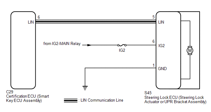
The steering lock ECU (steering lock actuator or UPR bracket assembly) is not connected to the CAN communication system. However, the steering lock ECU (steering lock actuator or UPR bracket assembly) is connected to the certification ECU (smart key ECU assembly) via LIN communication and communicates with other components via CAN communication through the certification ECU (smart key ECU assembly).
|
DTC No. |
Detection Item |
DTC Detection Condition |
Trouble Area |
Note |
|---|---|---|---|---|
|
B2788 |
IG2 Signal Malfunction |
Mismatch between the steering lock ECU (steering lock actuator or UPR bracket assembly) IG2 input from the LIN communication system and from the direct line (1-trip detection logic*). |
|
DTC Output Confirmation Operation: No confirmation operation is necessary (monitoring is continuous). |
- *: Only output while a malfunction is present and the engine switch is on (IG).
|
Vehicle Condition when Malfunction Detected |
Fail-safe Function when Malfunction Detected |
|---|---|
|
The steering cannot be locked or unlocked. For this reason, the engine cannot be started. |
- |
|
DTC No. |
Data List Item |
Active Test Item |
|---|---|---|
|
B2788 |
- |
- |
WIRING DIAGRAM
CAUTION / NOTICE / HINT
NOTICE:
- When using the Techstream with the engine switch off, connect the Techstream to the vehicle and turn a courtesy light switch on and off at intervals of 1.5 seconds or less until communication between the Techstream and the vehicle begins. Then select the vehicle type under manual mode and enter the following menus: Body Electrical / Smart Key. While using the Techstream, periodically turn a courtesy light switch on and off at intervals of 1.5 seconds or less to maintain communication between the Techstream and the vehicle.
- The steering lock system uses LIN communication. First perform the inspections
in "How to Proceed with Troubleshooting" to confirm that there are no communication
malfunctions before proceeding with troubleshooting (See page
.gif) ).
). - Inspect the fuses for circuits related to this system before performing the following procedure.
- After performing repairs, confirm that no DTCs are output again (See
page ).
- When replacing the steering lock ECU (steering lock actuator or UPR
bracket assembly), registration must be performed (See page
).
PROCEDURE
|
1. |
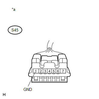
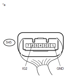
INSPECT STEERING LOCK ECU (STEERING LOCK ACTUATOR OR UPR BRACKET ASSEMBLY) (POWER SOURCE MODE SIGNAL) |
(a) Make sure that there is no looseness at the locking part and the connecting part of the connector.
(b) Disconnect the steering lock ECU (steering lock actuator or UPR bracket assembly) connector.
|
(c) Measure the resistance according to the value(s) in the table below. Standard Resistance:
|
|
(d) Reconnect the steering lock ECU (steering lock actuator or UPR bracket assembly) connector.
|
(e) Measure the voltage according to the value(s) in the table below. Standard Voltage:
|
|
| OK | .gif) |
REPLACE STEERING LOCK ECU (STEERING LOCK ACTUATOR OR UPR BRACKET ASSEMBLY) |
| NG | |
REPAIR OR REPLACE HARNESS OR CONNECTOR |
 Power Source Control ECU Malfunction (B2782)
DESCRIPTION
DESCRIPTION The certification ECU (smart key ECU assembly) has a power source
mode switching function.
This DTC is stored when the IGE input (the steering lock motor activation permiss ...
 Unable to Lock Steering Wheel
DESCRIPTION
The steering lock actuator assembly activates the steering lock motor and moves
the lock bar into the steering column to lock the steering.
When the steering lock is operating, the ste ...
Other materials:
Disassembly
DISASSEMBLY
CAUTION / NOTICE / HINT
HINT:
Use the same procedures for both the LH and RH sides.
The procedure described below is for the LH side.
PROCEDURE
1. REMOVE OUTER MIRROR
(a) Push the lower part of the mirror surface and tilt it.
Text in Illustration
...
Removal
REMOVAL
PROCEDURE
1. REMOVE REAR SEAT CUSHION ASSEMBLY
(a) Remove the 6 bolts and 2 rear seat cushion assemblies.
2. REMOVE NO. 4 ROOM PARTITION COVER LH
3. REMOVE NO. 4 ROOM PARTITION COVER RH
4. REMOVE NO. 3 ROOM PARTITION COVER
...
Wireless Charger Main Switch
Components
COMPONENTS
ILLUSTRATION
Removal
REMOVAL
PROCEDURE
1. REMOVE INSTRUMENT PANEL LOWER CENTER FINISH PANEL
(See page )
2. REMOVE MOBILE WIRELESS CHARGER SWITCH
(a) Disengage the 2 claws to remove the mobile wireless charger switch.
...
