Toyota Tacoma (2015-2018) Service Manual: Tire Pressure Warning Receiver
Components
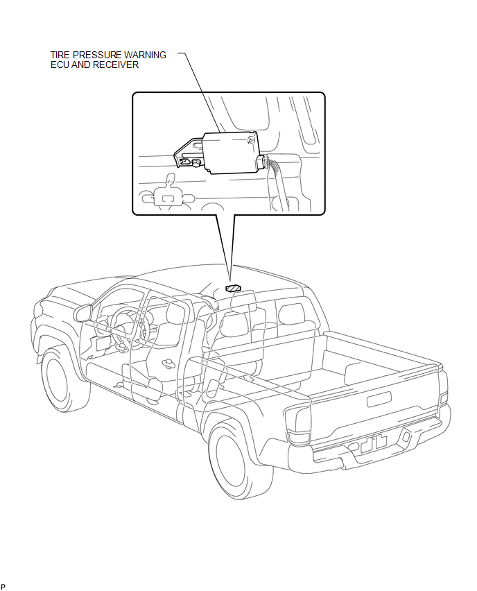
COMPONENTS
ILLUSTRATION
Removal
REMOVAL
PROCEDURE
1. SEPARATE ROOF HEADLINING ASSEMBLY (for Double Cab)
(See page .gif) )
)
2. SEPARATE ROOF HEADLINING ASSEMBLY (for Access Cab)
(See page )
3. REMOVE TIRE PRESSURE WARNING ECU AND RECEIVER
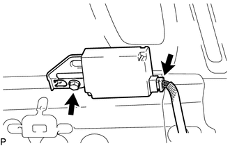
(a) Disconnect the connector.
(b) Remove the bolt and the tire pressure warning ECU and receiver.
Installation
INSTALLATION
PROCEDURE
1. INSTALL TIRE PRESSURE WARNING ECU AND RECEIVER
(a) Install the tire pressure warning ECU and receiver with the nut.
(b) Connect the connector.
2. INSTALL ROOF HEADLINING ASSEMBLY (for Double Cab)
(See page .gif) )
)
3. INSTALL ROOF HEADLINING ASSEMBLY (for Access Cab)
(See page )
4. REGISTRATION TRANSMITTER ID
(See page )
5. PERFORM INITIALIZATION
(See page )
 Precaution
PRECAUTION
1. REMOVAL AND INSTALLATION OF TIRE PRESSURE WARNING VALVE AND TRANSMITTER
(a) When installing a tire, make sure that the tire pressure warning valve and
transmitter does not interfere ...

Other materials:
Cellular Phone Inspection
PROCEDURE
1.
CHECK USAGE CONDITION
(a) Check that the vehicle and cellular phone meet the following conditions:
NOTICE:
If changing cellular phone settings, updating software, etc. is necessary, make
sure to obtain the permission of the customer before performin ...
Removal
REMOVAL
CAUTION / NOTICE / HINT
HINT:
Use the same procedure for both the RH and LH sides.
The procedure described below is for the LH side.
PROCEDURE
1. PRECAUTION
NOTICE:
After turning the ignition switch off, waiting time may be required before disconnecting
the cable f ...
Terminals Of Ecu
TERMINALS OF ECU
1. TERMINAL INSPECTION
Text in Illustration
*a
Component without harness connected
(Steering Lock ECU (Steering Lock Actuator or UPR Bracket Assembly))
-
-
(a) Measure the voltage and resistance according to the value(s) i ...
