Toyota Tacoma (2015-2018) Service Manual: Installation
INSTALLATION
PROCEDURE
1. INSTALL OIL COOLER TUBE
(a) Install the oil cooler tube to the vehicle body with the 2 bolts.
Torque:
28 N·m {286 kgf·cm, 21 ft·lbf}
2. INSTALL NO. 4 OIL COOLER INLET HOSE AND NO. 4 OIL COOLER OUTLET HOSE
NOTICE:
- When connecting the hoses to the tube, support the tube by hand and be careful to prevent the tube from being deformed.
- Make sure to install the clips so that the spool fitting is not overlapped.
(a) Install the No. 4 oil cooler inlet hose and No. 4 oil cooler outlet hose to the radiator assembly, and slide the 2 clips to secure them.
NOTICE:
Make sure to install any hose clips without a specific installation direction in a direction that does not interfere with other parts.
(b) Connect the No. 4 oil cooler inlet hose and No. 4 oil cooler outlet hose to the oil cooler tube, and slide the 2 clips to secure them.
NOTICE:
Make sure to install any hose clips without a specific installation direction in a direction that does not interfere with other parts.
(c) Then pass the No. 4 oil cooler inlet hose and No. 4 oil cooler outlet hose through the clamp and close the clamp.
3. INSTALL NO. 1 OIL COOLER INLET HOSE AND NO. 1 OIL COOLER OUTLET HOSE
NOTICE:
- When connecting the hoses to the tube, support the tube by hand and be careful to prevent the tube from being deformed.
- Make sure to install the clips so that the spool fitting is not overlapped.
(a) Install the No. 1 oil cooler inlet hose and No. 1 oil cooler outlet hose to the oil cooler tube, and slide the 2 clips to secure them.
NOTICE:
Make sure to install any hose clips without a specific installation direction in a direction that does not interfere with other parts.
4. INSTALL NO. 1 OIL COOLER INLET TUBE AND NO. 1 OIL COOLER OUTLET TUBE
NOTICE:
- When connecting the hoses to the tube, support the tube by hand and be careful to prevent the tube from being deformed.
- Make sure to install the clips so that the spool fitting is not overlapped.
(a) Install the 2 oil cooler tube clamps to the engine assembly with the 2 bolts.
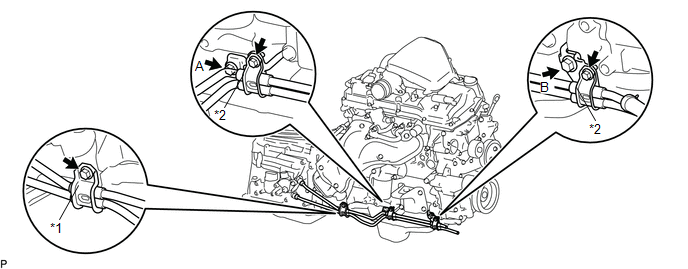 Text in Illustration
|
*1 |
Flexible Hose Clamp |
*2 |
Oil Cooler Tube Clamp |
Torque:
for Bolt A :
14 N·m {143 kgf·cm, 10 ft·lbf}
for Bolt B :
28 N·m {286 kgf·cm, 21 ft·lbf}
(b) Connect the ends of the No. 1 oil cooler inlet tube and No. 1 oil cooler outlet tube to the automatic transmission assembly by hand.
(c) Close the 2 oil cooler tube clamps and install the 2 bolts.
Torque:
5.5 N·m {56 kgf·cm, 49 in·lbf}
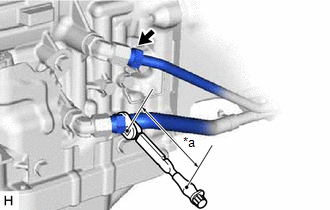
(d) Install the flexible hose clamp to the automatic transmission assembly with the bolt.
Torque:
14 N·m {143 kgf·cm, 10 ft·lbf}
(e) Connect the No. 1 oil cooler inlet hose and No. 1 oil cooler outlet hose to the No. 1 oil cooler inlet tube and No. 1 oil cooler outlet tube, and slide the 2 clips to secure them.
|
(f) Using a 17 mm union nut wrench, tighten the No. 1 oil cooler inlet tube and No. 1 oil cooler outlet tube. Text in Illustration
Torque: Specified tightening torque : 34 N·m {350 kgf·cm, 25 ft·lbf} HINT:
|
|
5. INSTALL FRONT EXHAUST PIPE ASSEMBLY
(See page .gif) )
)
6. ADD AUTOMATIC TRANSMISSION FLUID
(See page )
7. INSPECT FOR AUTOMATIC TRANSMISSION FLUID LEAK
8. INSTALL NO. 1 ENGINE UNDER COVER SUB-ASSEMBLY
Torque:
30 N·m {306 kgf·cm, 22 ft·lbf}
 Components
COMPONENTS
ILLUSTRATION
ILLUSTRATION
...
 Removal
REMOVAL
PROCEDURE
1. REMOVE NO. 1 ENGINE UNDER COVER SUB-ASSEMBLY
2. REMOVE FRONT EXHAUST PIPE ASSEMBLY
(See page )
3. REMOVE NO. 1 OIL COOLER INLET TUBE AND NO. 1 OIL COOLER OUTLET TUBE
NOTIC ...
Other materials:
Lost Communication with ECM / PCM "A" (U0100,U0129,U0142,U0151,U0163,U023A,U1104)
DESCRIPTION
The combination meter communicates with the ECM, skid control ECU, power steering
ECU, main body ECU (multiplex network body ECU), airbag sensor assembly, navigation
receiver assembly*1, radio and display receiver assembly*2, Forward recognition
camera*3 and Millimeter wave radar ...
Fail-safe Chart
FAIL-SAFE CHART
1. FAIL SAFE OPERATION
If there is a problem with any sensor signals or hydraulic brake booster
systems, the skid control ECU prohibits the power supply to the actuator
in the hydraulic brake booster and informs the ECM of VSC system failure.
The hydraulic brake b ...
USB Media Malfunction (B1585)
DESCRIPTION
This DTC is stored when a malfunction occurs in a connected device.
DTC No.
DTC Detection Condition
Trouble Area
B1585
USB Device Malfunction
Non mass-storage class or incompatible protocol USB device
...
