Toyota Tacoma (2015-2018) Service Manual: TS and CG Terminal Circuit
DESCRIPTION
In Test Mode (signal check), a malfunction in the speed sensor that cannot be detected when the vehicle is stopped can be detected while driving.
Sensor check mode can be entered by connecting terminals TS and CG of the DLC3 and turning the ignition switch from off to ON.
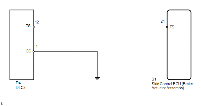
WIRING DIAGRAM
CAUTION / NOTICE / HINT
NOTICE:
When replacing the skid control ECU (brake actuator assembly), perform zero point
calibration and store system information (See page
.gif) ).
).
PROCEDURE
|
1. |
CHECK HARNESS AND CONNECTOR (BRAKE ACTUATOR ASSEMBLY - TS of DLC3) |
(a) Turn the ignition switch off.
(b) Disconnect the S1 skid control ECU (brake actuator assembly) connector.
(c) Measure the resistance according to the value(s) in the table below.
Standard Resistance:
|
Tester Connection |
Condition |
Specified Condition |
|---|---|---|
|
S1-24 (TS) - D4-12 (TS) |
Always |
Below 1 Ω |
|
S1-24 (TS) or D4-12 (TS) - Body ground |
Always |
10 kΩ or higher |
| NG | .gif) |
REPAIR OR REPLACE HARNESS OR CONNECTOR |
|
.gif)
|
2. |
CHECK HARNESS AND CONNECTOR (CG of DLC3 - BODY GROUND) |
|
(a) Measure the resistance according to the value(s) in the table below. Standard Resistance:
|
|
.png)
| OK | |
REPLACE BRAKE ACTUATOR ASSEMBLY |
| NG | |
REPAIR OR REPLACE HARNESS OR CONNECTOR |
 VSC Buzzer Circuit
DESCRIPTION
The skid control ECU (brake actuator assembly) is connected to the combination
meter via CAN communication.
The combination meter has a built-in VSC warning buzzer:
Sounds inte ...
 VSC OFF Switch Circuit
DESCRIPTION
The skid control ECU assembly is connected to the combination meter assembly
via CAN communication.
Pressing the VSC OFF switch turns off TRAC operation, and pressing and holding
thi ...
Other materials:
Air Conditioning Compressor Magnetic Clutch Circuit
DESCRIPTION
When the air conditioning amplifier assembly is turned on, a magnetic clutch
on signal is sent from the MGC terminal of the air conditioning amplifier assembly.
Then, the MG CLT relay turns on to operate the magnetic clutch assembly.
WIRING DIAGRAM
CAUTION / NOTICE / HINT
NO ...
Acceleration Sensor Internal Circuit (C1419,C1435)
DESCRIPTION
The skid control ECU (brake actuator assembly) receives signals from the yaw
rate and acceleration sensor (airbag sensor assembly) via the CAN communication
system.
The airbag sensor assembly has a built-in yaw rate and acceleration sensor and
detects the vehicle condition.
If t ...
Hydraulic Test
HYDRAULIC TEST
1. PERFORM HYDRAULIC TEST
(a) Measure the line pressure.
CAUTION:
The line pressure test should always be performed with at least 2 people. One
person should observe the condition of the wheels and wheel chocks while the other
is performing the test.
NOTICE:
Perform ...
