Toyota Tacoma (2015-2018) Service Manual: Terminals Of Ecu
TERMINALS OF ECU
1. CHECK TIRE PRESSURE WARNING ECU AND RECEIVER
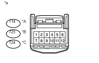
(a) Disconnect the T14 tire pressure warning ECU and receiver connector and measure the voltage and resistance on the wire harness side.
 Text in Illustration
|
*A |
w/o Wireless Door Lock System |
|
*B |
w/o Smart Key System with Wireless Door Lock System |
|
*C |
w/ Smart Key System |
|
*a |
Front view of wire harness connector (to Tire Pressure Warning ECU and Receiver) |
|
Terminal No. (Symbol) |
Wiring Color |
Terminal Description |
Condition |
Specified Condition |
|---|---|---|---|---|
|
T14-1 (IG) - T14-12 (GND) |
LG - W-B |
IG power source |
Ignition switch ON |
10 to 16 V |
|
T14-12 (GND) - Body ground |
W-B - Body ground |
Ground |
Always |
Below 1 Ω |
|
Terminal No. (Symbol) |
Wiring Color |
Terminal Description |
Condition |
Specified Condition |
|---|---|---|---|---|
|
T25-1 (IG) - T25-12 (GND) |
LG - W-B |
IG power source |
Ignition switch ON |
10 to 16 V |
|
T25-7 (+B) - T25-12 (GND |
BE - W-B |
Power supply (from battery) |
Always |
10 to 16 V |
|
T25-12 (GND) - Body ground |
W-B - Body ground |
Ground |
Always |
Below 1 Ω |
|
Terminal No. (Symbol) |
Wiring Color |
Terminal Description |
Condition |
Specified Condition |
|---|---|---|---|---|
|
T24-1 (IG) - T24-12 (GND) |
LG - W-B |
IG power source |
Ignition switch ON |
10 to 16 V |
|
T24-7 (+B) - T24-12 (GND) |
BE - W-B |
Power supply (from battery) |
Always |
10 to 16 V |
|
T24-12 (GND) - Body ground*1 |
W-B - Body ground |
Ground |
Always |
Below 1 Ω |
(b) Connect the T14*1, T25*2, T24*3 tire pressure warning ECU and receiver connector.
(c) Measure the voltage and resistance according to the value(s) in the table below. If the result is not as specified, the ECU may be malfunctioning.
HINT:
Measure the values on the wire harness side while the connector is connected.

|
Terminal No. (Symbol) |
Wiring Color |
Terminal Description |
Condition |
Specified Condition |
|---|---|---|---|---|
|
T14-3 (CLSW) - T14-12 (GND)*1 T25-3 (CLSW) - T25-12 (GND)*2 T24-3 (CLSW) - T24-12 (GND)*3 |
R - W-B |
Tire pressure warning reset switch |
|
Below 1.5 V |
|
8 to 15 V |
|||
|
T14-4 (RDA) - T14-12 (GND)*1 T25-4 (RDA) - T25-12 (GND)*2 T24-4 (RDA) - T24-12 (GND)*3 |
B - W-B |
Output signals |
Ignition switch ON |
Pulse generation (see waveform 1) |
|
T14-5 (PRG) - T14-12 (GND)*1 T25-5 (PRG) - T25-12 (GND)*2 T24-5 (PRG) - T24-12 (GND)*3 |
GR - W-B |
Input signals |
Ignition switch ON |
Pulse generation (see waveform 1) |
- *1: w/o Wireless Door Lock System
- *2: w/o Smart Key System with Wireless Door Lock System
- *3: w/ Smart Key System
(d) Using an oscilloscope, check waveform 1.
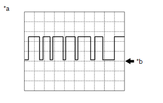
Waveform 1:
|
Item |
Contents |
|---|---|
|
Terminal |
T14-4 (RDA) - T14-12 (GND)*1 T25-4 (RDA) - T25-12 (GND)*2 T24-4 (RDA) - T24-12 (GND)*3 T14-5 (PRG) - T14-12 (GND)*1 T25-5 (PRG) - T25-12 (GND)*2 T24-5 (PRG) - T24-12 (GND)*3 |
|
Tool setting |
5 V/DIV., 5 ms./DIV. |
|
Vehicle condition |
Ignition switch ON |
- *1: w/o Wireless Door Lock System
- *2: w/o Smart Key System with Wireless Door Lock System
- *3: w/ Smart Key System
|
*a |
Example |
|
*b |
GND |
HINT:
The waveform shown in the illustration is an example. If the tester displays a waveform that alternates between high and low, where high is a voltage that is between the IG power source voltage and a voltage 2.2 V lower than the IG power source voltage, and where low is a voltage of between 0 and 1.2 V, the ECU can be judged normal.
 Problem Symptoms Table
PROBLEM SYMPTOMS TABLE
HINT:
Use the table below to help determine the cause of problem symptoms.
If multiple suspected areas are listed, the potential causes of the symptoms
are lis ...
 Test Mode Procedure
TEST MODE PROCEDURE
1. TEST MODE (SIGNAL CHECK MODE) PROCEDURE
HINT:
When entering test mode (signal check mode), the tire pressure warning
ECU and receiver stores all the test mode (si ...
Other materials:
Components
COMPONENTS
ILLUSTRATION
*1
CHARCOAL CANISTER ASSEMBLY
*2
CHARCOAL CANISTER FUEL HOSE
*3
CHARCOAL CANISTER LEAK DETECTION PUMP SUB-ASSEMBLY
*4
FUEL TANK VENT HOSE
*5
FUEL TANK ...
If the shift lever cannot be shifted from P (vehicles with an automatic transmission)
If the shift lever cannot be shifted with your foot on the brake, there may
be a problem with the shift lock system (a system to prevent accidental operation
of the shift lever). Have the vehicle inspected by your Toyota dealer immediately.
The following steps may be used as an emergency measur ...
Utility
UTILITY
NOTICE:
If the forward recognition camera has been replaced with a new one or
the windshield glass has been removed and installed, it is necessary to
perform Forward Recognition Camera Axis Adjustment. If the system is turned
on without performing Forward Recognition Ca ...
