Toyota Tacoma (2015-2018) Service Manual: System Diagram
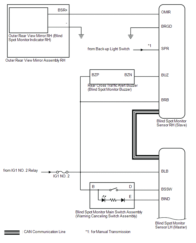
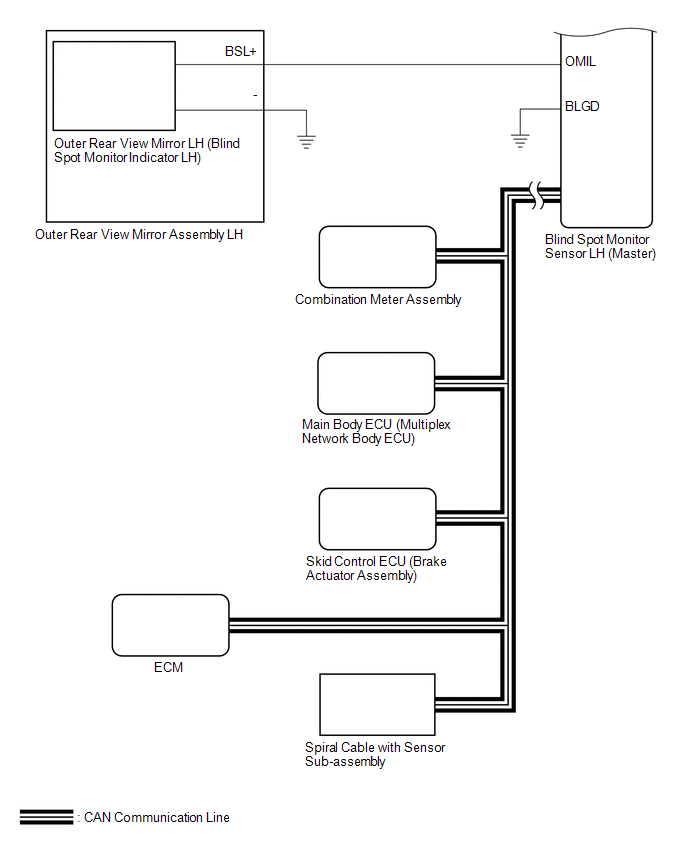
SYSTEM DIAGRAM
 System Description
SYSTEM DESCRIPTION
1. GENERAL
(a) The blind spot monitor system has the blind spot monitor function and rear
cross traffic alert function.
(1) Blind spot monitor function
The blind spot m ...
 How To Proceed With Troubleshooting
CAUTION / NOTICE / HINT
HINT:
Use the following procedure to troubleshoot the blind spot monitor system.
*: Use the Techstream.
PROCEDURE
1.
VEHICLE BRO ...
Other materials:
System Voltage Circuit Short to Ground or Open (P056014)
DESCRIPTION
The battery supplies power to the ECM even when the ignition switch is off. This
power allows the ECM to store data such as DTC history, freeze frame data and fuel
trim values. If the battery voltage falls below a minimum level, the ECM data is
cleared and the ECM determines that ...
Installation
INSTALLATION
PROCEDURE
1. INSTALL FRONT NO. 2 SPEAKER ASSEMBLY RH
(a) Connect the connector.
(b) Install the front No. 2 speaker assembly RH with the 2 bolts.
Torque:
8.4 N·m {86 kgf·cm, 74 in·lbf}
NOTICE:
Do not touch the cone part of the front No. 2 speaker assembly RH.
...
Removal
REMOVAL
PROCEDURE
1. REMOVE FRONT CONSOLE BOX
(See page )
2. DISCONNECT TRANSMISSION CONTROL CABLE ASSEMBLY
(a) Move the shift lever to N.
(b) Disconnect the end of the transmission control cable assembly from the transmission
floor shift assembly.
Text in Illustration
...
