Toyota Tacoma (2015-2018) Service Manual: System Description
SYSTEM DESCRIPTION
1. GENERAL
(a) The blind spot monitor system has the blind spot monitor function and rear cross traffic alert function.
(1) Blind spot monitor function
- The blind spot monitor function is a function that assists the driver in making the decision to change lanes. The function uses quasi-millimeter wave radar to detect vehicles that are traveling in an adjacent lane in the area that is not reflected in the outer rear view mirror assembly. The function advises the driver of the existence of a vehicle by illuminating the outer rear view mirror indicator on the outer rear view mirror assembly.
- If the turn signal switch is operated while the outer rear view mirror indicator on an outer rear view mirror assembly is illuminated, the indicator starts blinking to give additional warning to the driver.
(2) Rear cross traffic alert function
- The rear cross traffic alert function is a function that informs the driver of an approaching vehicle from diagonally behind. The function uses quasi-millimeter wave radar to detect the positions of and relative speed to a vehicle. When the function determines that a vehicle is approaching this vehicle, this function informs the driver of it using the indicators and buzzer.
2. FUNCTION OF COMPONENTS
|
Component |
Function |
|---|---|
|
Blind Spot Monitor Sensor |
|
|
Outer Rear View Mirror Assembly
|
Turns on or blinks the indicator based on a signal from the blind spot monitor sensor. |
|
Blind Spot Monitor Main Switch Assembly (Warning Canceling Switch Assembly)
|
|
|
Rear Cross Traffic Alert Buzzer (Blind Spot Monitor Buzzer) |
Sounds based on a signal from the blind spot monitor sensor. |
|
Combination Meter Assembly
|
|
|
Main Body ECU (Multiplex Network Body ECU) |
Sends the destination information and the dimmer signal to the blind spot monitor sensor via CAN communication. |
|
Skid Control ECU (Brake Actuator Assembly) |
Transmits a vehicle speed signal to the blind spot monitor sensor via CAN communication. |
|
ECM |
Sends a shift position signal (R) to the blind spot monitor sensor via CAN communication.*1 |
|
Back-up Light Switch Assembly |
Sends a shift position signal (R) to the blind spot monitor sensor.*2 |
|
Spiral Cable with Sensor Sub-assembly |
Detects the angle of the steering wheel and sends the resulting signals to the blind spot monitor sensor via CAN communication. |
- *1: for Automatic Transmission
- *2: for Manual Transmission
3. OPERATION DESCRIPTION
(a) Operation description of the blind spot monitor function
(1) Operation conditions
- The blind spot monitor main switch assembly (warning canceling switch assembly) is on.
- Vehicle speed is more than approximately 16 km/h (10 mph).
(2) Conditions in which a sensor can detect a vehicle
The blind spot monitor function indicates detection of a vehicle in the detection area when either condition is met:
- When a vehicle is detected in an adjacent lane overtaking this vehicle.
- When a vehicle is detected entering the detection area because it changed lanes.
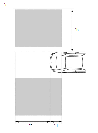
(3) Detection area
Vehicles in the following areas can be detected:
 Text in Illustration
|
*a |
Vehicles in the following areas can be detected: |
|
*b |
Within approximately 3.5 m (11.49 ft.) from the side of the vehicle |
|
*c |
Within approximately 3 m (9.85 ft.) behind the rear bumper |
|
*d |
Within approximately 1 m (3.29 ft.) forward of the rear bumper |
(b) Operation description of the rear cross traffic alert function.
(1) Operation conditions:
- The blind spot monitor main switch assembly (warning canceling switch assembly) is on.
- The shift lever is in R.
- The vehicle speed is less than approximately 8 km/h (5 mph).
(2) Conditions in which a sensor can detect a vehicle
The rear cross traffic alert function indicates detection of a vehicle in the detection area when both conditions are met:
- A vehicle is approaching this vehicle from diagonally behind.
- The vehicle speed is approximately 8 km/h (5 mph) to 28 km/h (18 mph).
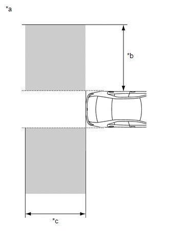
(3) Detection area
Vehicles in the following areas can be detected:
 Text in Illustration
|
*a |
Vehicles in the following areas can be detected: |
|
*b |
Within approximately 5.5 to 20 m (18.04 to 65.62 ft.) from the side of the vehicle (detection area changes according to vehicle speed) |
|
*c |
Within approximately 6 m (19.69 ft.) behind the rear bumper |
4. OPERATION OF OUTER REAR VIEW MIRROR INDICATOR AND REAR CROSS TRAFFIC ALERT BUZZER (BLIND SPOT MONITOR BUZZER)
(a) Initial check
(1) When the blind spot monitor main switch assembly (warning canceling switch assembly) is turned on with the ignition switch ON, the outer rear view mirror indicator on each outer rear view mirror assembly illuminates for 3 seconds and the rear cross traffic alert buzzer assembly (blind spot monitor buzzer) sounds for 1 second.
(2) When the ignition switch is turned from off to ON with the blind spot monitor main switch assembly (warning canceling switch assembly) on, the outer rear view mirror indicator on each outer rear view mirror assembly illuminates for 3 seconds.
(b) Operation for each function
(1) Operation for blind spot monitor function
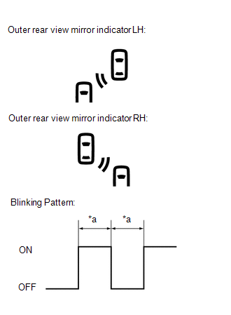
- When a sensor detects a vehicle in the blind spot area, the outer rear view mirror indicator on the outer rear view mirror assembly illuminates.
- While the sensor is detecting a vehicle in the detection area and the indicator is illuminated, if the turn signal switch is operated, the outer rear view mirror indicator on the outer rear view mirror assembly starts blinking as shown in the illustration.
 Text in Illustration
|
*a |
0.125 seconds |
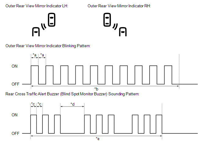
(2) Operation for rear cross traffic alert function
- When all of the operation conditions for the rear cross traffic alert function are met, the outer rear view mirror indicators on the outer rear view mirror assembly blink for 2.5 seconds and the rear cross traffic alert buzzer (blind spot monitor buzzer) sounds for 2.3 seconds as shown in the illustration.
 Text in Illustration
|
*a |
0.125 seconds |
*b |
2.5 seconds |
|
*c |
0.1 seconds |
*d |
0.4 seconds |
|
*e |
2.3 seconds |
- |
- |
 Parts Location
PARTS LOCATION
ILLUSTRATION
ILLUSTRATION
...
 System Diagram
SYSTEM DIAGRAM
...
Other materials:
Rear Speed Sensor RH Malfunction (C1403,C1404)
DESCRIPTION
The speed sensor detects wheel speed and sends the appropriate signals to the
skid control ECU (brake actuator assembly). These signals are used for brake control.
The speed sensor rotors have rows of alternating N and S magnetic poles and their
magnetic fields change when the roto ...
Cruise Control System Internal Failure (P057504,P057549)
DESCRIPTION
This DTC is stored when there is a malfunction in the ECM.
DTC No.
Detection Item
DTC Detection Condition
Trouble Area
MIL
P057504
Cruise Control System Internal Failure
While the dynamic rada ...
Installation
INSTALLATION
PROCEDURE
1. INSTALL FRONT CRANKSHAFT OIL SEAL
(a) Using SST and a hammer, tap in a new oil seal until its surface is
flush with the timing chain cover assembly edge.
SST: 09223-22010
SST: 09506-35010
NOTICE:
Keep the lip free from foreign matt ...
