Toyota Tacoma (2015-2018) Service Manual: Reassembly
REASSEMBLY
PROCEDURE
1. INSTALL STARTER ARMATURE ASSEMBLY
(a) Install the starter armature to the starter yoke.
2. INSTALL STARTER BRUSH HOLDER ASSEMBLY
(a) Install the starter brush holder assembly.
|
(b) Connect the 4 brushes to the starter brush holder assembly. (1) Using a screwdriver, hold back the brush spring. (2) Connect the brush to the starter brush holder assembly. NOTICE: Check that the positive (+) lead wires are not grounded. |
|
.png)
(c) Place a new O-ring in position on the commutator end frame.
|
(d) Install the commutator end frame with the 2 screws. Torque: 1.5 N·m {15 kgf·cm, 13 in·lbf} |
|
.png)
3. INSTALL MAGNET STARTER SWITCH ASSEMBLY
(a) Apply high-temperature grease to the idle gear, steel ball, return spring, clutch roller and retainer.
|
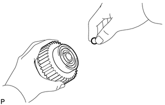
(b) Insert the steel ball into the starter clutch hole. |
|
|
(c) Insert the return spring into the starter clutch hole. Text Illustration
|
|
.png)
(d) Install the starter clutch sub-assembly, idle gear, retainer and clutch roller to the starter drive housing assembly.
|
(e) Install the starter drive housing assembly to the magnet starter switch assembly with the 2 bolts. Torque: 5.9 N·m {60 kgf·cm, 52 in·lbf} |
|
.png)
4. INSTALL STARTER YOKE ASSEMBLY
(a) Install a new O-ring to the groove of the starter yoke assembly.
|
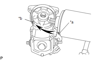
(b) Align the claw of the starter yoke assembly with the groove of the starter switch. Text in Illustration
|
|
|
(c) Install the starter yoke assembly to the magnet starter switch assembly with the 2 bolts. Torque: 5.9 N·m {60 kgf·cm, 52 in·lbf} |
|
.png)
(d) Connect the lead wire to terminal C with the nut.
Torque:
5.9 N·m {60 kgf·cm, 52 in·lbf}
 Installation
INSTALLATION
PROCEDURE
1. INSTALL FLYWHEEL HOUSING SIDE COVER
(a) Install the flywheel housing side cover to the cylinder block sub-assembly.
2. INSTALL STARTER ASSEMBLY
(a) Install the starter a ...
 Starter Relay
Inspection
INSPECTION
PROCEDURE
1. INSPECT STARTER RELAY
(a) Check the resistance.
(1) Measure the resistance according to the value(s) in the table below.
Standard Resistance:
...
Other materials:
Disassembly
DISASSEMBLY
PROCEDURE
1. REMOVE FRONT BRAKE SHOE
(a) Using SST, remove the shoe return spring from the front brake shoe.
SST: 09921-00010
(b) Using needle-nose pliers, remove the return spring.
(c) Using SST, remove the shoe hol ...
Data List / Active Test
DATA LIST / ACTIVE TEST
1. READ DATA LIST
HINT:
Using the Techstream to read the Data List allows the values or states of switches,
sensors, actuators and other items to be read without removing any parts. This non-intrusive
inspection can be very useful because intermittent conditions or sig ...
Operation Check
OPERATION CHECK
1. CHECK WIRELESS CHARGING SYSTEM OPERATION
(a) Turn the ignition switch ON (IG or ACC).
(b) Press the mobile wireless charger switch and check that the switch indicator
light illuminates.
Text in Illustration
*a
Switch Indicator Light
(c) Plac ...
