Toyota Tacoma (2015-2018) Service Manual: System Diagram
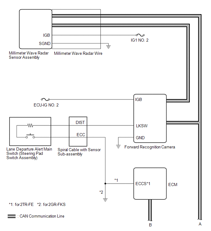
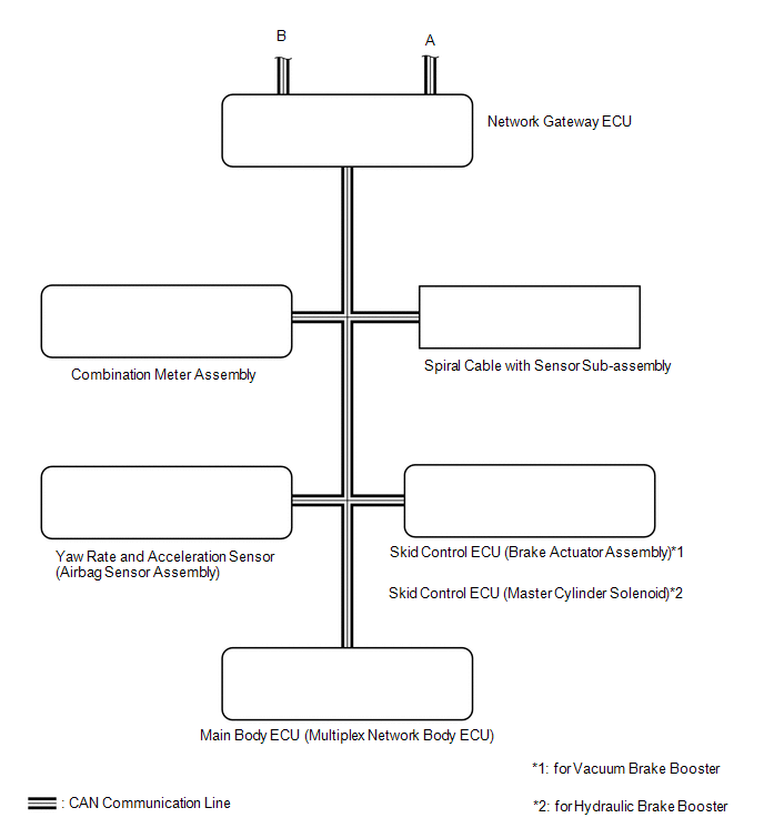
SYSTEM DIAGRAM
 Communication Table
|
Sender ECU |
Receiver ECU |
Signal |
Line |
|---|---|---|---|
| *1: for Vacuum Brake Booster
*2: for Hydraulic Brake Booster |
|||
|
Forward Recognition Camera |
Combination Meter Assembly |
|
CAN |
|
ECM |
Forward Recognition Camera |
|
CAN |
|
|
CAN |
|
|
Combination Meter Assembly |
|
CAN |
|
|
Spiral Cable with Sensor Sub-assembly |
|
CAN |
|
|
Yaw Rate and Acceleration Sensor (Airbag Sensor Assembly) |
|
CAN |
|
|
Main Body ECU (Multiplex Network Body ECU) |
|
CAN |
|
 System Description
SYSTEM DESCRIPTION
LANE DEPARTURE ALERT SYSTEM DESCRIPTION
(a) The lane departure alert system is a system which uses the forward recognition
camera to recognize and determine the lane and the pos ...
 How To Proceed With Troubleshooting
CAUTION / NOTICE / HINT
HINT:
Use these procedures to troubleshoot the lane departure alert system.
*: Use the Techstream.
PROCEDURE
1.
VEHICLE BROUGHT ...
Other materials:
Manual Transmission Unit
Components
COMPONENTS
ILLUSTRATION
ILLUSTRATION
*1
SHIFT DETENT BALL PLUG
*2
SHIFT DETENT BALL COMPRESSION SPRING
*3
MANUAL TRANSMISSION FILLER PLUG
*4
SHAFT DETENT BALL
*5
...
Transmission Control Switch Circuit
DESCRIPTION
After moving the shift lever to S, it is possible to switch the shift range between
"1" (S1 range) and "6" (S6 range) using the transmission control switch.
Moving the shift lever to "+" once raises the shift range by one, and moving
the shift lever to ...
Unable to Lock Steering Wheel
DESCRIPTION
The steering lock actuator assembly activates the steering lock motor and moves
the lock bar into the steering column to lock the steering.
When the steering lock is operating, the steering may not lock when the lock
bar is not aligned with the lock hole of the steering column. In ...
