Toyota Tacoma (2015-2018) Service Manual: Transmission Control Switch Circuit
DESCRIPTION
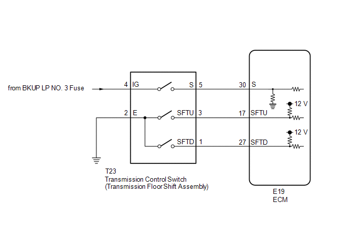
After moving the shift lever to S, it is possible to switch the shift range between "1" (S1 range) and "6" (S6 range) using the transmission control switch.
Moving the shift lever to "+" once raises the shift range by one, and moving the shift lever to "-" once lowers the shift range by one.
WIRING DIAGRAM
CAUTION / NOTICE / HINT
NOTICE:
Inspect the fuses for circuits related to this system before performing the following inspection procedure.
PROCEDURE
|
1. |
READ VALUE USING TECHSTREAM (SPORTS MODE SELECTION SW) |
(a) Connect the Techstream to the DLC3.
(b) Turn the ignition switch to ON.
(c) Turn the Techstream on.
(d) Enter the following menus: Powertrain / Engine and ECT / Data List.
(e) In accordance with the display on the Techstream, read the Data List.
Engine and ECT|
Tester Display |
Measurement Item/Range |
Normal Condition |
Diagnostic Note |
|---|---|---|---|
|
Sports Mode Selection SW |
Sport mode select switch status/ ON or OFF |
|
- |
|
Result |
Proceed to |
|---|---|
|
Data display is within Normal Condition range |
A |
|
Data display is not within Normal Condition range |
B |
| B | .gif) |
GO TO STEP 6 |
|
.gif)
|
2. |
READ VALUE USING TECHSTREAM (SPORTS SHIFT UP SW AND SPORTS SHIFT DOWN SW) |
(a) Connect the Techstream to the DLC3.
(b) Turn the ignition switch to ON.
(c) Turn the Techstream on.
(d) Enter the following menus: Powertrain / Engine and ECT / Data List.
(e) In accordance with the display on the Techstream, read the Data List.
Engine and ECT|
Tester Display |
Measurement Item/Range |
Normal Condition |
Diagnostic Note |
|---|---|---|---|
|
Sports Shift Up SW |
Sport shift up switch status/ ON or OFF |
|
- |
|
Sports Shift Down SW |
Sport shift down switch status/ ON or OFF |
|
- |
|
Result |
Proceed to |
|---|---|
|
Data display is within Normal Condition range |
A |
|
Data display is not within Normal Condition range |
B |
| A | |
PROCEED TO NEXT SUSPECTED AREA SHOWN IN PROBLEM SYMPTOMS TABLE |
|
|
3. |
INSPECT TRANSMISSION CONTROL SWITCH (TRANSMISSION FLOOR SHIFT ASSEMBLY) |
|
(a) Disconnect T23 transmission control switch (transmission floor shift assembly) connector. |
|
(b) Measure the resistance according to the value(s) in the table below.
Standard Resistance:
|
Tester Connection |
Condition |
Specified Condition |
|---|---|---|
|
3 (SFTU) - 2 (E) |
Shift lever held in "+" (Up-shift) |
Below 1 Ω |
|
1 (SFTD) - 2 (E) |
Shift lever held in "-" (Down-shift) |
Below 1 Ω |
|
3 (SFTU) - 2 (E) |
Shift lever not held in "+" |
10 kΩ or higher |
|
1 (SFTD) - 2 (E) |
Shift lever not held in "-" |
10 kΩ or higher |
|
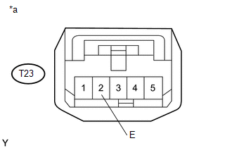
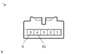
*a |
Component without harness connected (Transmission Control Switch (Transmission Floor Shift Assembly)) |
| NG | |
REPLACE TRANSMISSION CONTROL SWITCH (TRANSMISSION FLOOR SHIFT ASSEMBLY) |
|
|
4. |
CHECK HARNESS AND CONNECTOR (TRANSMISSION CONTROL SWITCH (TRANSMISSION FLOOR SHIFT ASSEMBLY) - BODY GROUND) |
|
(a) Disconnect the transmission control switch (transmission floor shift assembly) connector. |
|
(b) Measure the resistance according to the value(s) in the table below.
Standard Resistance:
|
Tester Connection |
Condition |
Specified Condition |
|---|---|---|
|
T23-2 (E) - Body ground |
Always |
Below 1 Ω |
|
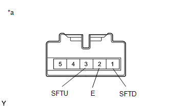
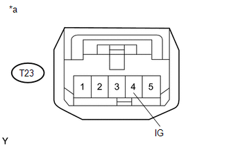
*a |
Front view of wire harness connector (to Transmission Control Switch (Transmission Floor Shift Assembly)) |
| NG | |
REPAIR OR REPLACE HARNESS OR CONNECTOR |
|
|
5. |
CHECK HARNESS AND CONNECTOR (TRANSMISSION CONTROL SWITCH - ECM) |
|
(a) Disconnect the ECM connector. |
|
(b) Measure the resistance according to the value(s) in the table below.
Standard Resistance:
|
Tester Connection |
Condition |
Specified Condition |
|---|---|---|
|
E19-17 (SFTU) - Body ground |
Shift lever held in "+" (Up-shift) |
Below 1 Ω |
|
E19-27 (SFTD) - Body ground |
Shift lever held in "-" (Down-shift) |
Below 1 Ω |
|
E19-17 (SFTU) - Body ground and other terminals |
Shift lever not held in "+" |
10 kΩ or higher |
|
E19-27 (SFTD) - Body ground and other terminals |
Shift lever not held in "-" |
10 kΩ or higher |
|
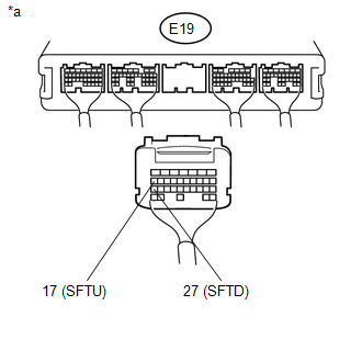
*a |
Rear view of wire harness connector (to ECM) |
| OK | |
PROCEED TO NEXT SUSPECTED AREA SHOWN IN PROBLEM SYMPTOMS TABLE |
| NG | |
REPAIR OR REPLACE HARNESS OR CONNECTOR |
|
6. |
INSPECT TRANSMISSION CONTROL SWITCH (TRANSMISSION FLOOR SHIFT ASSEMBLY) |
|
(a) Disconnect T23 transmission control switch (transmission floor shift assembly) connector. |
|
(b) Measure the resistance according to the value(s) in the table below.
Standard Resistance:
|
Tester Connection |
Condition |
Specified Condition |
|---|---|---|
|
4 (IG) - 5 (S) |
Shift lever in S, "+" or "- " |
Below 1 Ω |
|
4 (IG) - 5 (S) |
Shift lever not in S, "+" or "-" |
10 kΩ or higher |
|
*a |
Component without harness connected (Transmission Control Switch (Transmission Floor Shift Assembly)) |
| NG | |
REPLACE TRANSMISSION CONTROL SWITCH (TRANSMISSION FLOOR SHIFT ASSEMBLY) |
|
|
7. |
CHECK HARNESS AND CONNECTOR (BATTERY - TRANSMISSION CONTROL SWITCH (TRANSMISSION FLOOR SHIFT ASSEMBLY)) |
|
(a) Disconnect the transmission control switch (transmission floor shift assembly) connector. |
|
(b) Measure the voltage according to the value(s) in the table below.
Standard Voltage:
|
Tester Connection |
Switch Condition |
Specified Condition |
|---|---|---|
|
T23-4 (IG) - Body ground |
Ignition switch ON |
11 to 14 V |
|
T23-4 (IG) - Body ground |
Ignition switch off |
Below 1 V |
|
*a |
Front view of wire harness connector (to Transmission Control Switch (Transmission Floor Shift Assembly)) |
| NG | |
REPAIR OR REPLACE HARNESS OR CONNECTOR |
|
|
8. |
CHECK HARNESS AND CONNECTOR (TRANSMISSION CONTROL SWITCH (TRANSMISSION FLOOR SHIFT ASSEMBLY) - ECM) |
(a) Disconnect the T23 transmission control switch (transmission floor shift assembly) connector.
(b) Disconnect the E19 ECM connector.
(c) Measure the resistance according to the value(s) in the table below.
Standard Resistance:
|
Tester Connection |
Condition |
Specified Condition |
|---|---|---|
|
T23-5 (S) - E19-30 (S) |
Always |
Below 1 Ω |
|
T23-5 (S) - Body ground |
Always |
10 kΩ or higher |
|
E19-30 (S) - Body ground |
Always |
10 kΩ or higher |
| OK | |
PROCEED TO NEXT SUSPECTED AREA SHOWN IN PROBLEM SYMPTOMS TABLE |
| NG | |
REPAIR OR REPLACE HARNESS OR CONNECTOR |
 Pattern Select Switch Power Mode Circuit
DESCRIPTION
The ECM memory contains the programs for the normal and PWR shift patterns.
By following the programs corresponding to the signals from the pattern select
switch assembly, park/neutral ...
 Extension Housing Rear Oil Seal
Components
COMPONENTS
ILLUSTRATION
Replacement
REPLACEMENT
PROCEDURE
1. REMOVE PROPELLER SHAFT WITH CENTER BEARING ASSEMBLY
(See page )
2. REMOVE AUTOMATIC TRANSMISSION EXTENSION HOUSIN ...
Other materials:
Control Module Communication Bus OFF (U0073,U0100,U0114,U0123,U0124,U0126)
DESCRIPTION
The skid control ECU (master cylinder solenoid) receives the signals from the
ECM, steering angle sensor (spiral cable with sensor sub-assembly), 4 wheel drive
control ECU*, and yaw rate and acceleration sensor (airbag sensor assembly) via
the CAN communication system.
*: ...
Luggage compartment features
Behind the rear seat (Double
Cab models only)
1.Cargo net hooks (vehicles with sub woofer)
2.Grocery bag hooks
3.Flashlight holder
4.Storage boxes
Deck
1. Auxiliary boxes
2. Tie-down cleats
3. Deck hooks
Auxiliary boxes
Left side
1. Turn the knob counterclockwise.
2. Open the ...
Removal
REMOVAL
PROCEDURE
1. REMOVE PROPELLER SHAFT WITH CENTER BEARING ASSEMBLY
(a) Place matchmarks on the propeller shaft flange and differential flange.
Text in Illustration
*a
Matchmark
...
