Toyota Tacoma (2015-2018) Service Manual: System Diagram
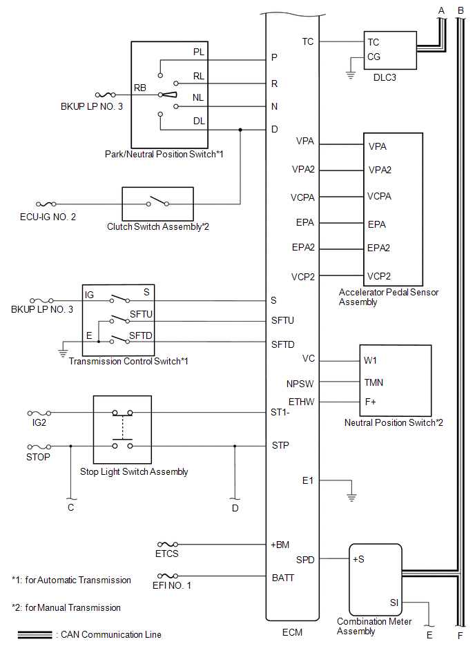
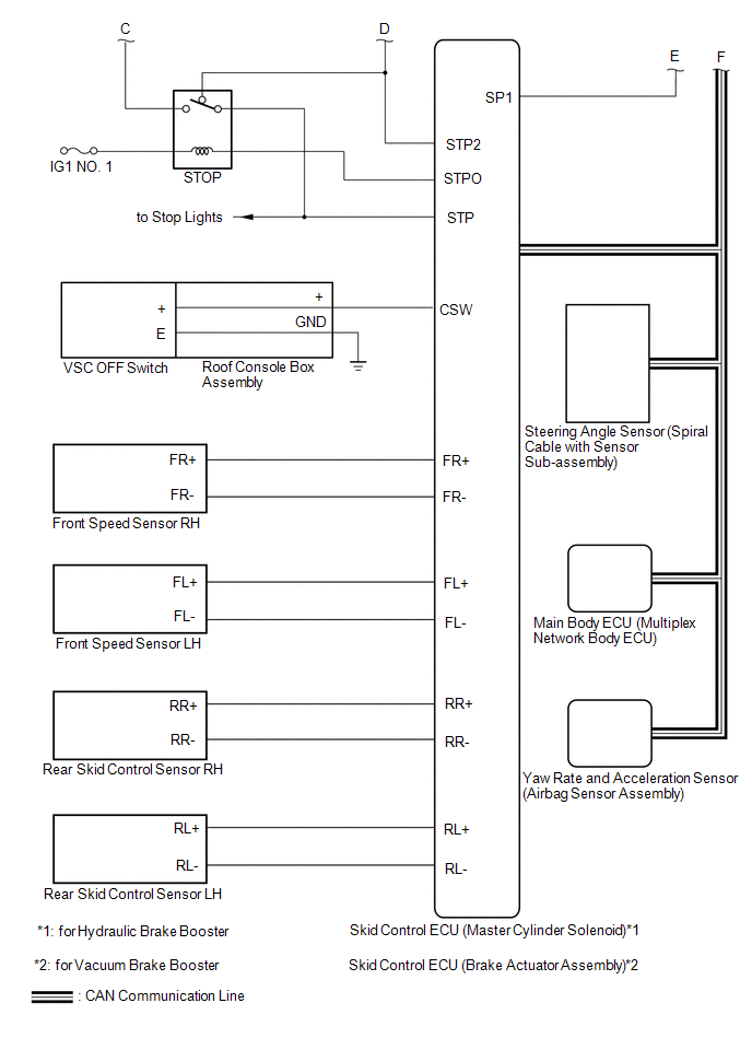
SYSTEM DIAGRAM
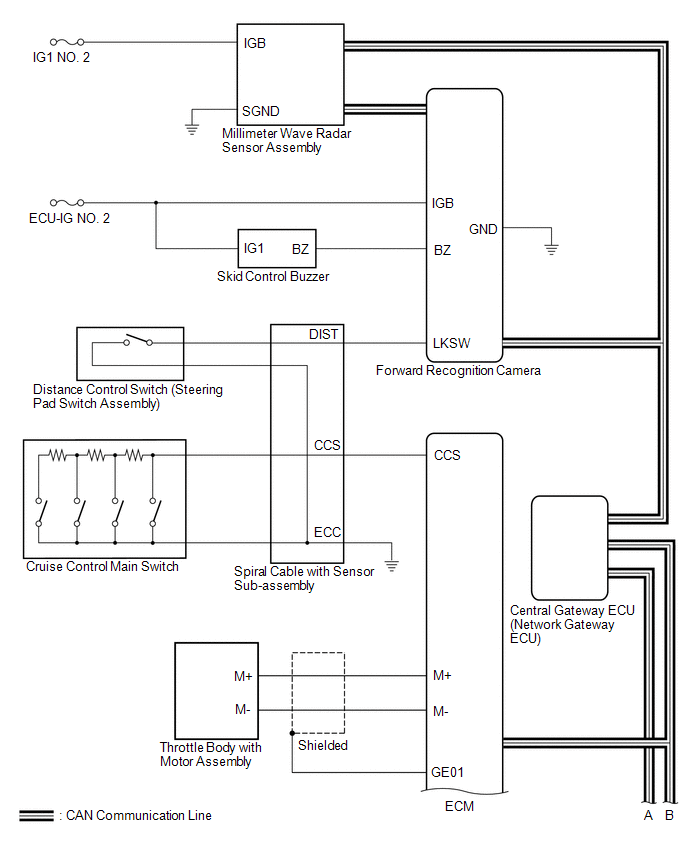
 Communication Table
|
Sender |
Receiver |
Signal |
Line |
|---|---|---|---|
|
ECM |
Millimeter Wave Radar Sensor Assembly |
|
CAN |
|
ECM |
Skid Control ECU (Master Cylinder Solenoid)*1 Skid Control ECU (Brake Actuator Assembly)*2 |
|
CAN |
|
ECM |
Combination Meter Assembly |
|
CAN |
|
ECM |
Forward Recognition Camera |
Cruise control operation signal |
CAN |
|
Millimeter Wave Radar Sensor Assembly |
ECM |
|
CAN |
|
Millimeter Wave Radar Sensor Assembly |
Combination Meter Assembly |
Millimeter wave radar sensor beam axis deviation signal |
CAN |
|
Skid Control ECU (Master Cylinder Solenoid)*1 Skid Control ECU (Brake Actuator Assembly)*2 |
Millimeter Wave Radar Sensor Assembly |
|
CAN |
|
Skid Control ECU (Master Cylinder Solenoid)*1 Skid Control ECU (Brake Actuator Assembly)*2 |
ECM |
|
CAN |
|
Steering Angle Sensor (Spiral Cable with Sensor Sub-assembly) |
Millimeter Wave Radar Sensor Assembly |
|
CAN |
|
Main Body ECU (Multiplex Network Body ECU) |
Millimeter Wave Radar Sensor Assembly |
Destination information signal |
CAN |
|
Yaw Rate and Acceleration Sensor (Airbag Sensor Assembly) |
Millimeter Wave Radar Sensor Assembly |
|
CAN |
- *1: for Hydraulic Brake Booster
- *2: for Vacuum Brake Booster
 Parts Location
PARTS LOCATION
ILLUSTRATION
*A
for Hydraulic Brake Booster
*B
for Vacuum Brake Booster
*C
for Automatic Transmission
...
 How To Proceed With Troubleshooting
CAUTION / NOTICE / HINT
HINT:
Perform the following procedure to troubleshoot the dynamic radar cruise
control system.
*: Use the Techstream.
PROCEDURE
1.
...
Other materials:
Removal
REMOVAL
PROCEDURE
1. DISCONNECT TRANSMISSION WIRE
(See page )
2. REMOVE VALVE BODY OIL STRAINER ASSEMBLY
(a) Remove the 3 bolts and valve body oil strainer assembly from the
transmission valve body assembly.
3. REMOVE TRANSMISSION VALVE ...
Dtc Check / Clear
DTC CHECK / CLEAR
CHECK FOR DTC
(a) Connect the Techstream to the DLC3.
(b) Turn the ignition switch to ON.
(c) Turn the Techstream on.
(d) Enter the following menus: Body Electrical / Central Gateway / Trouble Codes.
(e) Read the DTCs.
CLEAR DTC
(a) Connect the Techstream to the DLC3.
(b) ...
Data List / Active Test
DATA LIST / ACTIVE TEST
1. DATA LIST
NOTICE:
In the table below, the values listed under "Normal Condition" are reference
values. Do not depend solely on these reference values when deciding whether a part
is faulty or not.
HINT:
Using the Techstream to read the Data List allows t ...
