Toyota Tacoma (2015-2018) Service Manual: Parts Location
PARTS LOCATION
ILLUSTRATION
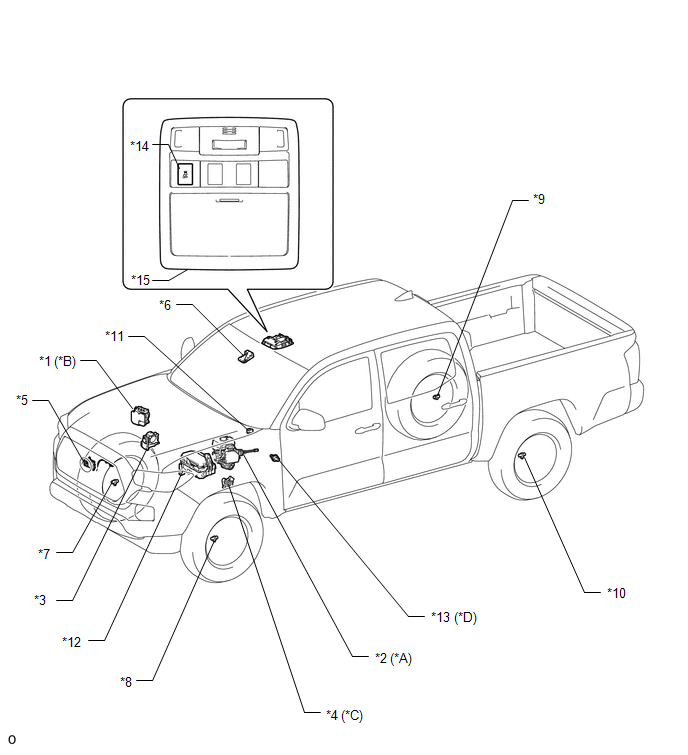
|
*A |
for Hydraulic Brake Booster |
*B |
for Vacuum Brake Booster |
|
*C |
for Automatic Transmission |
*D |
for Manual Transmission |
|
*1 |
SKID CONTROL ECU (BRAKE ACTUATOR ASSEMBLY) |
*2 |
SKID CONTROL ECU (MASTER CYLINDER SOLENOID) |
|
*3 |
THROTTLE BODY WITH MOTOR ASSEMBLY |
*4 |
PARK/NEUTRAL POSITION SWITCH |
|
*5 |
MILLIMETER WAVE RADAR SENSOR ASSEMBLY |
*6 |
FORWARD RECOGNITION CAMERA |
|
*7 |
FRONT SPEED SENSOR RH |
*8 |
FRONT SPEED SENSOR LH |
|
*9 |
REAR SPEED SENSOR RH |
*10 |
REAR SPEED SENSOR LH |
|
*11 |
SKID CONTROL BUZZER |
*12 |
ENGINE ROOM RELAY BLOCK - IG2 FUSE - EFI NO. 1 FUSE - ETCS FUSE - STOP FUSE - STOP RELAY |
|
*13 |
NEUTRAL POSITION SWITCH |
*14 |
VSC OFF SWITCH |
|
*15 |
ROOF CONSOLE BOX ASSEMBLY |
- |
- |
ILLUSTRATION
|
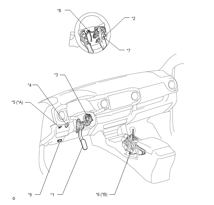
*A |
for Manual Transmission |
*B |
for Automatic Transmission |
|
*1 |
ACCELERATOR PEDAL SENSOR ASSEMBLY |
*2 |
CRUISE CONTROL MAIN SWITCH |
|
*3 |
STEERING ANGLE SENSOR (SPIRAL CABLE WITH SENSOR SUB-ASSEMBLY) |
*4 |
STOP LIGHT SWITCH ASSEMBLY |
|
*5 |
CLUTCH SWITCH ASSEMBLY |
*6 |
TRANSMISSION CONTROL SWITCH (TRANSMISSION FLOOR SHIFT ASSEMBLY ) |
|
*7 |
DISTANCE CONTROL SWITCH (STEERING PAD SWITCH ASSEMBLY) |
*8 |
CRUISE CONTROL SWITCH WIRE |
|
*9 |
DLC3 |
- |
- |
ILLUSTRATION
|
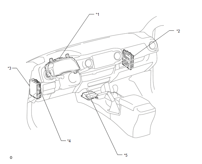
*1 |
COMBINATION METER ASSEMBLY |
*2 |
ECM |
|
*3 |
DRIVER SIDE JUNCTION BLOCK - IG1 NO. 2 FUSE - ECU-IG NO. 2 FUSE - IG1 NO. 1 FUSE - BKUP LP NO. 3 FUSE |
*4 |
MAIN BODY ECU (MULTIPLEX NETWORK BODY ECU) |
|
*5 |
YAW RATE AND ACCELERATION SENSOR (AIRBAG SENSOR ASSEMBLY) |
- |
- |
 Definition Of Terms
DEFINITION OF TERMS
Term
Definition
Monitor Description
Description of what the ECM monitors and how it detects malfunctions
(monitoring purpose ...
 System Diagram
SYSTEM DIAGRAM
Communication Table
Sender
Receiver
Signal
Line
ECM
Millimeter Wave Radar Sensor Assembly
...
Other materials:
4WD ECU Malfunction (P163B)
DESCRIPTION
This DTC is output when a malfunction is detected in the 4 wheel drive control
ECU internal circuit.
DTC No.
Detection Item
DTC Detection Condition
Trouble Area
P163B
4WD ECU Malfunction
Dia ...
Dtc Check / Clear
DTC CHECK / CLEAR
CHECK DTC
(a) Connect the Techstream to the DLC3.
(b) Turn the ignition switch to ON.
(c) Turn the Techstream on.
(d) Enter the following menus: Chassis / LKA/LDA / Trouble Codes.
(e) Check for DTCs.
Click here
CLEAR DTC
(a) Connect the Techstream to the DLC3.
(b) Turn ...
Brake
General Maintenance
GENERAL MAINTENANCE
PROCEDURE
1. INSPECT BRAKE LINE PIPES AND HOSES
HINT:
Work in a well-lighted area. Turn the front wheels fully to the right or left
before beginning.
(a) Check all the brake lines and hoses for:
Damage
Wear
Deformation
Cracks
...
