Toyota Tacoma (2015-2018) Service Manual: Stereo Component Amplifier Power Source Circuit
DESCRIPTION
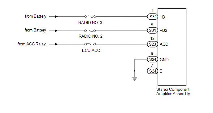
This circuit provides power to the stereo component amplifier assembly.
WIRING DIAGRAM
CAUTION / NOTICE / HINT
Inspect the fuses for circuits related to this system before performing the following inspection procedure.
PROCEDURE
|
1. |
CHECK HARNESS AND CONNECTOR (STEREO COMPONENT AMPLIFIER ASSEMBLY POWER SOURCE) |
|
(a) Disconnect the stereo component amplifier assembly connectors. |
|
(b) Measure the resistance according to the value(s) in the table below.
Standard Resistance:
|
Tester Connection |
Condition |
Specified Condition |
|---|---|---|
|
S24-6 (GND) - Body ground |
Always |
Below 1 Ω |
|
S24-7 (E) - Body ground |
Always |
Below 1 Ω |
(c) Measure the voltage according to the value(s) in the table below.
Standard Voltage:
|
Tester Connection |
Switch Condition |
Specified Condition |
|---|---|---|
|
S31-1 (+B) - S24-6 (GND) |
Always |
11 to 14 V |
|
S31-5 (+B2) - S24-6 (GND) |
Always |
11 to 14 V |
|
S23-12 (ACC) - S24-6 (GND) |
Ignition switch ACC |
11 to 14 V |
|
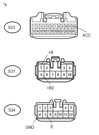
*a |
Front view of wire harness connector (to Stereo Component Amplifier Assembly) |
| OK | .gif) |
PROCEED TO NEXT SUSPECTED AREA SHOWN IN PROBLEM SYMPTOMS TABLE |
| NG | |
REPAIR OR REPLACE HARNESS AND CONNECTOR |
 Radio Receiver Power Source Circuit
DESCRIPTION
This is the power source circuit to operate the navigation receiver assembly.
WIRING DIAGRAM
CAUTION / NOTICE / HINT
NOTICE:
Inspect the fuses for circuits related to this s ...

Other materials:
Brake Switch "A" Circuit Open (P057113)
DESCRIPTION
When the brakes are applied by the dynamic radar cruise control system, the skid
control ECU (master cylinder solenoid)*1 or skid control ECU (brake actuator assembly)*2
operates the stop light switch assembly (stop light relay) to illuminate the stop
lights.
If the ECM receives ...
Vehicle Information Not Obtained (C1A02)
DESCRIPTION
When a new millimeter wave radar sensor assembly is installed, it receives vehicle
specification information (destination, steering wheel position, 2WD or 4WD, etc.)
from the main body ECU (multiplex network body ECU) and stores the information.
DTC C1A02 is stored when the millime ...
Terminals Of Ecu
TERMINALS OF ECU
1. CHECK AIR CONDITIONING AMPLIFIER ASSEMBLY (for Automatic Air Conditioning)
(See page )
2. CHECK AIR CONDITIONING AMPLIFIER ASSEMBLY (for Manual Air Conditioning)
(See page )
3. CHECK AIR CONDITIONING CONTROL ASSEMBLY (for Automatic Air Conditioning)
(See page )
4. CHECK ...
