Toyota Tacoma (2015-2018) Service Manual: 4wd Control Ecu
Components
COMPONENTS
ILLUSTRATION
Installation
INSTALLATION
PROCEDURE
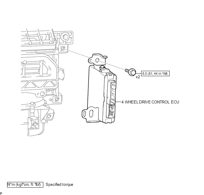
1. INSTALL 4 WHEEL DRIVE CONTROL ECU
(a) Engage the 2 guides to install the 4 wheel drive control ECU.
(b) Install the 2 bolts.
Torque:
5.0 N·m {51 kgf·cm, 44 in·lbf}
(c) Connect the 2 connectors.
2. INSTALL ECM
(See page .gif) )
)
Removal
REMOVAL
PROCEDURE
1. REMOVE ECM
(See page .gif) )
)
2. REMOVE 4 WHEEL DRIVE CONTROL ECU
|
(a) Disconnect the 2 connectors. |
|
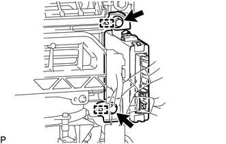
(b) Remove the 2 bolts.
(c) Disengage the 2 guides to remove the 4 wheel drive control ECU.
 Vf2cm Transfer
...

Other materials:
Removal
REMOVAL
PROCEDURE
1. REMOVE RADIATOR GRILLE
(a) w/ Toyota Safety Sense P
(1) Disconnect the connector.
(2) Disengage the clamp.
(b) Put protective tape around the radiator grille.
...
Removal
REMOVAL
PROCEDURE
1. PRECAUTION
NOTICE:
After turning the ignition switch off, waiting time may be required before disconnecting
the cable from the negative (-) battery terminal.
Therefore, make sure to read the disconnecting the cable from the negative (-)
battery terminal notices before p ...
Vehicle Speed Signal Circuit between Stereo Component Amplifier and Combination
Meter
DESCRIPTION
The stereo component amplifier assembly receives a vehicle speed signal from
the combination meter assembly to control the ASL function.
HINT:
A voltage of 12 V or 5 V is output from each ECU and then input to the
combination meter assembly. The signal is changed to a pu ...
