Toyota Tacoma (2015-2018) Service Manual: Radio Receiver Power Source Circuit
DESCRIPTION
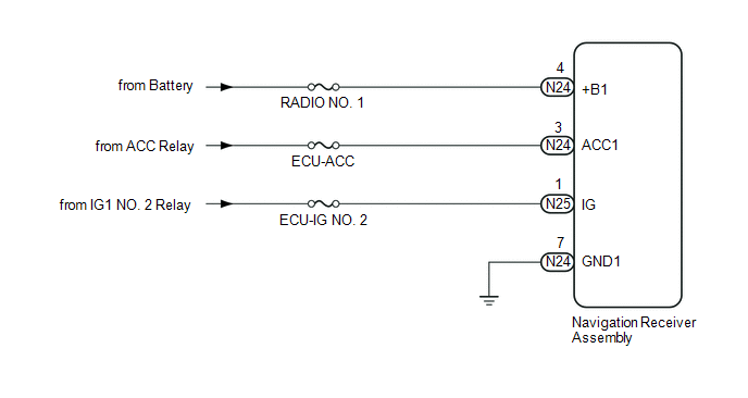
This is the power source circuit to operate the navigation receiver assembly.
WIRING DIAGRAM
CAUTION / NOTICE / HINT
NOTICE:
- Inspect the fuses for circuits related to this system before performing the following inspection procedure.
PROCEDURE
|
1. |
CHECK HARNESS AND CONNECTOR (NAVIGATION RECEIVER ASSEMBLY - BATTERY AND BODY GROUND) |
|
(a) Disconnect the N24 and N25 navigation receiver assembly connectors. |
|
(b) Measure the resistance according to the value(s) in the table below.
Standard Resistance:
|
Tester Connection |
Condition |
Specified Condition |
|---|---|---|
|
N24-7 (GND1) - Body ground |
Always |
Below 1 Ω |
(c) Measure the voltage according to the value(s) in the table below.
Standard Voltage:
|
Tester Connection |
Switch Condition |
Specified Condition |
|---|---|---|
|
N24-4 (+B1) - N24-7 (GND1) |
Always |
11 to 14 V |
|
N24-3 (ACC1) - N24-7 (GND1) |
Ignition switch ACC |
11 to 14 V |
|
N25-1 (IG) - N24-7 (GND1) |
Ignition switch ON |
11 to 14 V |
|
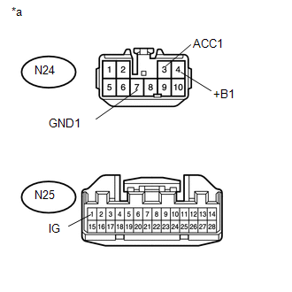
*a |
Front view of wire harness connector (to Navigation Receiver Assembly) |
| OK | .gif) |
PROCEED TO NEXT SUSPECTED AREA SHOWN IN PROBLEM SYMPTOMS TABLE |
| NG | |
REPAIR OR REPLACE HARNESS OR CONNECTOR |
 Microphone Circuit between Microphone and Radio Receiver
DESCRIPTION
The navigation receiver assembly and telephone microphone assembly are connected
to each other using the microphone connection detection signal lines.
Using this circuit, the navigatio ...
 Stereo Component Amplifier Power Source Circuit
DESCRIPTION
This circuit provides power to the stereo component amplifier assembly.
WIRING DIAGRAM
CAUTION / NOTICE / HINT
Inspect the fuses for circuits related to this system before performing ...
Other materials:
Cruise Control Switch Circuit
DESCRIPTION
The cruise control main switch is used to turn the dynamic radar cruise control
system on and off, as well as operate 7 functions: SET, - (COAST), TAP-DOWN, RES
(RESUME), + (ACCEL), TAP-UP and CANCEL.
The SET, TAP-DOWN and - (COAST) functions, and the RES (RESUME), TAP-UP and +
( ...
Front Radar Sensor Beam Axis Not Adjusted (C1A14)
DESCRIPTION
After installing a new millimeter wave radar sensor assembly, if sensor beam
axis adjustment has not been performed, DTC C1A14 will be stored.
DTC No.
Detection Item
DTC Detection Condition
Trouble Area
C1A14
Fro ...
Automatic High Beam System (B124B)
DESCRIPTION
The main body ECU (multiplex network body ECU) determines the status of the automatic
high beam system based on the automatic high beam system signal from the forward
recognition camera.
DTC No.
Detection Item
DTC Detection Condition
Trou ...
