Toyota Tacoma (2005–2015) Owners Manual: Automatic transmission
Select a shift position appropriate for the driving conditions.
■ Shifting the shift lever
 5-speed models
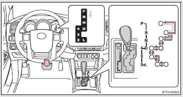
 While the engine switch is on, depress
the brake pedal and move the shift lever.
While the engine switch is on, depress
the brake pedal and move the shift lever.
4-speed models
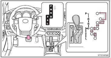
 While the engine switch is on, depress
the brake pedal and move the shift lever.
While the engine switch is on, depress
the brake pedal and move the shift lever.
■ Shift position uses
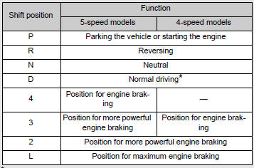
*: To improve fuel consumption and reduce noises, set the shift lever in D for normal driving.
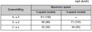
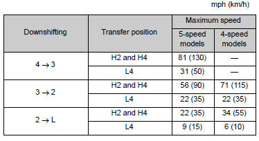
■Downshifting restrictions
The shift lever cannot be downshifted if the following speeds are exceeded.
 2WD models
4WD models
■When driving with the cruise control system (if equipped)
The engine brake will not operate when downshifting from D to 4 (5-speed models) or 3 (4-speed models).
■If the shift lever cannot be shifted from P
■AI-SHIFT
AI-SHIFT automatically selects the suitable gear according to driver performance and driving conditions.
AI-SHIFT automatically operates when the shift lever is in the D position.
The engine speed may remain high after releasing the accelerator pedal.
This does not indicate a malfunction.
 Engine (ignition) switch
■ Engine switch
LOCK
The steering wheel is locked and the key can be removed.
(Vehicles with an automatic transmission: The key can be removed only when the
shift lever is in P.)
ACC
...
 Manual transmission
■ Shifting the shift lever
6-speed models
Fully depress the clutch pedal before operating the shift lever, and then release
it slowly.
5-speed models
Fully depress the clutch pedal b ...
Other materials:
Installation
INSTALLATION
PROCEDURE
1. INSTALL REAR DIFFERENTIAL DRIVE PINION BEARING SPACER
(a) Install a new front differential drive pinion bearing spacer.
HINT:
Make sure the front differential drive pinion bearing spacer is installed correctly.
2. INSTALL DIFFERENTIAL OIL STORAGE RING
(a) Using a bra ...
Reservoir Level Switch Disconnected (C1453,C1454)
DESCRIPTION
The brake fluid level warning switch sends the appropriate signal to the skid
control ECU (master cylinder solenoid) when the brake fluid level drops.
DTC Code
DTC Detection Condition
Trouble Area
C1453
With the ECU termina ...
Brake Switch "A" Circuit Open (P057113)
DESCRIPTION
When the brakes are applied by the dynamic radar cruise control system, the skid
control ECU (master cylinder solenoid)*1 or skid control ECU (brake actuator assembly)*2
operates the stop light switch assembly (stop light relay) to illuminate the stop
lights.
If the ECM receives ...
