Toyota Tacoma (2015-2018) Service Manual: Steering Pad Switch
Components
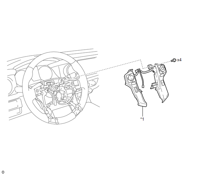
COMPONENTS
ILLUSTRATION
|
*1 |
STEERING PAD SWITCH ASSEMBLY |
- |
- |
Removal
REMOVAL
PROCEDURE
1. REMOVE STEERING PAD
(See page .gif) )
)
2. REMOVE STEERING PAD SWITCH ASSEMBLY
|
(a) Disconnect the 2 connectors. |
|
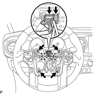
(b) Disengage the 2 clamps.
(c) Remove the 4 screws.
|
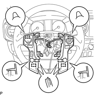
(d) Disengage the 6 guides and 2 claws to remove the steering pad switch assembly. NOTICE: Disengage the 2 guides on the upper part of the steering pad switch assembly first. |
|
Inspection
INSPECTION
PROCEDURE
1. INSPECT STEERING PAD SWITCH ASSEMBLY
(a) Measure the resistance according to the value(s) in the table below.
Standard resistance:
|
Tester Connection |
Switch Condition |
Specified Condition |
|---|---|---|
|
2 (+DP) - 8 (EAU) 3 (+DP2) - 8 (EAU) 10 (AU2) - 8 (EAU) 11 (AU1) - 8 (EAU) |
No switch is pushed |
100 kΩ or higher |
|
2 (+DP) - 8 (EAU) |
TOP switch is pushed |
329 Ω |
|
BACK switch is pushed |
1000 Ω |
|
|
ENTER switch is pushed |
Below 2.5 Ω |
|
|
3 (+DP2) - 8 (EAU) |
UP switch is pushed |
329 Ω |
|
DOWN switch is pushed |
1000 Ω |
|
|
RIGHT switch is pushed |
3110 Ω |
|
|
LEFT switch is pushed |
Below 2.5 Ω |
|
|
10 (AU2) - 8 (EAU) |
VOICE switch is pushed |
3110 Ω |
|
MODE switch is pushed |
Below 2.5 Ω |
|
|
OFF HOOK switch is pushed |
1000 Ω |
|
|
ON HOOK switch is pushed |
329 Ω |
|
|
11 (AU1) - 8 (EAU) |
VOLUME+ switch is pushed |
1000 Ω |
|
VOLUME- switch is pushed |
3110 Ω |
|
|
SEEK+ switch is pushed |
Below 2.5 Ω |
|
|
SEEK- switch is pushed |
329 Ω |
|
|
4 (DIST) - 7 (ECC) |
ACC switch is pushed |
Below 2.5 Ω |
|
LDA switch is pushed |
240Ω |
If the result is not as specified, replace the steering pad switch assembly.
Installation
INSTALLATION
PROCEDURE
1. INSTALL STEERING PAD SWITCH ASSEMBLY
(a) Engage the 6 guides and 2 claws to install the steering pad switch assembly.
(b) Install the 4 screws.
(c) Engage the 2 clamps.
(d) Connect the 2 connectors.
2. INSTALL STEERING PAD
(See page .gif) )
)
 Satellite Radio Tuner
Components
COMPONENTS
ILLUSTRATION
Removal
REMOVAL
PROCEDURE
1. REMOVE RADIO AND DISPLAY RECEIVER ASSEMBLY WITH BRACKET
(See page )
2. REMOVE NO. 1 NAVIGATION WIRE
(a) Disco ...
 Stereo Component Amplifier
Components
COMPONENTS
ILLUSTRATION
ILLUSTRATION
Removal
REMOVAL
PROCEDURE
1. PRECAUTION
NOTICE:
After turning the ignition switch off, waiting time may be required before disconnectin ...
Other materials:
Disposal
DISPOSAL
CAUTION / NOTICE / HINT
CAUTION:
Before performing pre-disposal deployment of any SRS part, review and closely
follow all applicable environmental and hazardous material regulations. Pre-disposal
deployment may be considered hazardous material treatment.
PROCEDURE
1. PRECAUTION
...
Open or Short in Master Cylinder Pressure Sensor (C1421,C1423,C1424,C142A,C1449)
DESCRIPTION
DTC No.
Detection Item
DTC Detection Condition
Trouble Area
C1421
Open or Short in Master Cylinder Pressure Sensor
Any of the following is detected:
When voltage at terminal +BS is 9.5 V or ...
Operation Check
OPERATION CHECK
1. CHECK WIRELESS CHARGING SYSTEM OPERATION
(a) Turn the ignition switch ON (IG or ACC).
(b) Press the mobile wireless charger switch and check that the switch indicator
light illuminates.
Text in Illustration
*a
Switch Indicator Light
(c) Plac ...
