Toyota Tacoma (2015-2018) Service Manual: Network Gateway Ecu
Components
COMPONENTS
ILLUSTRATION
Installation
INSTALLATION
PROCEDURE
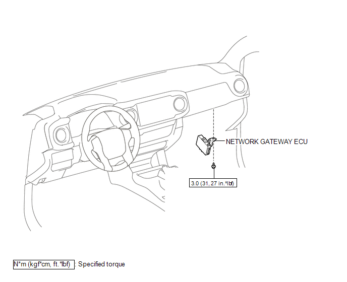
1. INSTALL NETWORK GATEWAY ECU
(a) Install the network gateway ECU with the bolt.
Torque:
3.0 N·m {31 kgf·cm, 27 in·lbf}
(b) Connect the connector.
2. INSTALL LOWER INSTRUMENT PANEL ASSEMBLY
(See page .gif) )
)
Removal
REMOVAL
PROCEDURE
1. REMOVE LOWER INSTRUMENT PANEL ASSEMBLY
(See page .gif) )
)
2. REMOVE NETWORK GATEWAY ECU
|
(a) Disconnect the connector. |
|
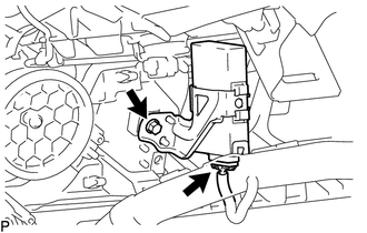
(b) Remove the bolt and network gateway ECU.
 Tire Pressure Monitor ECU Communication Stop Mode
DESCRIPTION
Detection Item
Symptom
Trouble Area
Tire Pressure Monitor ECU Communication Stop Mode
Either condition is met:
C ...

Other materials:
AUTO LSD Indicator Light Remains ON
DESCRIPTION
During normal mode, pressing the VSC OFF switch for a short amount of time changes
vehicle to AUTO LSD mode.
WIRING DIAGRAM
CAUTION / NOTICE / HINT
NOTICE:
When replacing the brake actuator assembly, perform calibration (See page
).
PROCEDURE
1.
CHECK ...
Fail-safe Chart
FAIL-SAFE CHART
HINT:
If any of the following auto cancel conditions are detected while the dynamic
radar cruise control system is controlling vehicle speed, the system clears the
stored vehicle speed and cancels control of vehicle speed by the dynamic radar cruise
control system.
Automatic ...
Disassembly
DISASSEMBLY
PROCEDURE
1. REMOVE OIL PUMP RELIEF VALVE
(a) Using a 27 mm socket wrench, remove the oil pump relief valve plug.
(b) Remove the oil pump relief valve spring and oil pump relief valve.
(c) Remove the spring and relief valve.
2. R ...
