Toyota Tacoma (2015-2018) Service Manual: Satellite Radio Tuner
Components
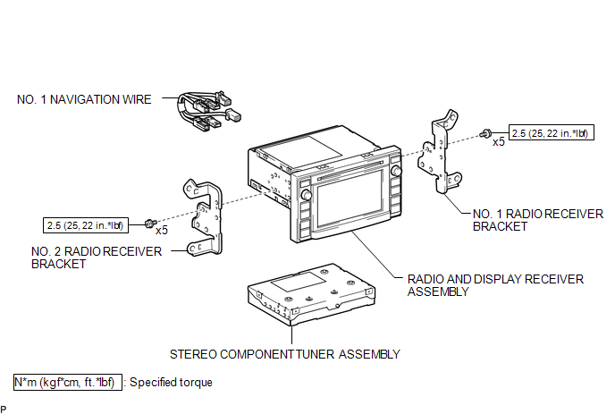
COMPONENTS
ILLUSTRATION
Removal
REMOVAL
PROCEDURE
1. REMOVE RADIO AND DISPLAY RECEIVER ASSEMBLY WITH BRACKET
(See page .gif) )
)
2. REMOVE NO. 1 NAVIGATION WIRE
|
(a) Disconnect the 6 connectors to remove the No. 1 navigation wire. |
|
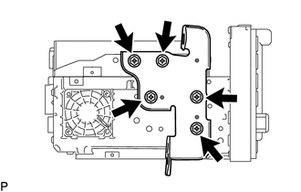
3. REMOVE NO. 1 RADIO RECEIVER BRACKET
|
(a) Remove the 5 bolts and No. 1 radio receiver bracket. |
|
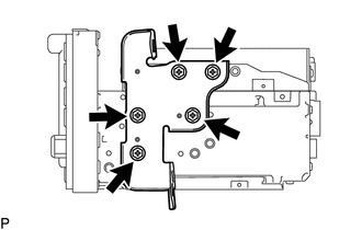
4. REMOVE NO. 2 RADIO RECEIVER BRACKET
|
(a) Remove the 5 bolts and No. 2 radio receiver bracket. |
|
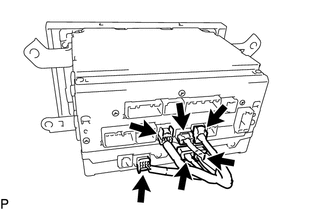
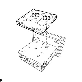
5. REMOVE STEREO COMPONENT TUNER ASSEMBLY
|
(a) Disengage the 2 guides to remove the stereo component tuner assembly as shown in the illustration. |
|
Installation
INSTALLATION
PROCEDURE
1. INSTALL STEREO COMPONENT TUNER ASSEMBLY
(a) Engage the 2 guides to install the stereo component tuner assembly.
2. INSTALL NO. 2 RADIO RECEIVER BRACKET
(a) Install the No. 2 radio receiver bracket with the 5 bolts.
Torque:
2.5 N·m {25 kgf·cm, 22 in·lbf}
3. INSTALL NO. 1 RADIO RECEIVER BRACKET
(a) Install the No. 1 radio receiver bracket with the 5 bolts.
Torque:
2.5 N·m {25 kgf·cm, 22 in·lbf}
4. INSTALL NO. 1 NAVIGATION WIRE
(a) Connect the 6 connectors to install the No. 1 navigation wire.
5. INSTALL RADIO AND DISPLAY RECEIVER ASSEMBLY WITH BRACKET
(See page .gif) )
)
 Installation
INSTALLATION
CAUTION / NOTICE / HINT
HINT:
Use the same procedure for the RH and LH sides.
The procedure listed below is for the LH side.
PROCEDURE
1. INSTALL REAR SPEAKER ASSEM ...
 Steering Pad Switch
Components
COMPONENTS
ILLUSTRATION
*1
STEERING PAD SWITCH ASSEMBLY
-
-
Removal
REMOVAL
PROCEDURE
1. REMOVE STEERING PAD
(See page )
...
Other materials:
Four-wheel drive system
Use the front-wheel drive control switch to select the following transfer modes.
H2 (high speed position, two-wheel
drive)
Use this for normal driving on dry hard-surfaced roads.
This position gives greater economy, quietest ride and least wear.
H4 (high speed position, four-wheel
drive) ...
Diagnostic Trouble Code Chart
DIAGNOSTIC TROUBLE CODE CHART
Rear View Monitor System
DTC Code
Detection Item
See page
C1622
Open or Short Circuit in Back Camera Signal
...
Tire Pressure Warning Receiver
Components
COMPONENTS
ILLUSTRATION
Removal
REMOVAL
PROCEDURE
1. SEPARATE ROOF HEADLINING ASSEMBLY (for Double Cab)
(See page )
2. SEPARATE ROOF HEADLINING ASSEMBLY (for Access Cab)
(See page )
3. REMOVE TIRE PRESSURE WARNING ECU AND RECEIVER
(a) Disconnect the connector.
(b) ...
