Toyota Tacoma (2015-2018) Service Manual: Stereo Component Amplifier
Components
COMPONENTS
ILLUSTRATION
.png)
ILLUSTRATION
Removal
REMOVAL
PROCEDURE
1. PRECAUTION
NOTICE:
After turning the ignition switch off, waiting time may be required before disconnecting the cable from the negative (-) battery terminal. Therefore, make sure to read the disconnecting the cable from the negative (-) battery terminal notices before proceeding with work.
Click here .gif)
2. DISCONNECT CABLE FROM NEGATIVE BATTERY TERMINAL
NOTICE:
When disconnecting the cable, some systems need to be initialized after the cable is reconnected.
Click here
3. REMOVE REAR SEATBACK ASSEMBLY RH
(See page )
4. REMOVE REAR SEATBACK ASSEMBLY LH
(See page )
5. REMOVE LUGGAGE COMPARTMENT SIDE TRAY LH
(See page )
6. REMOVE LUGGAGE COMPARTMENT SIDE TRAY RH
(See page )
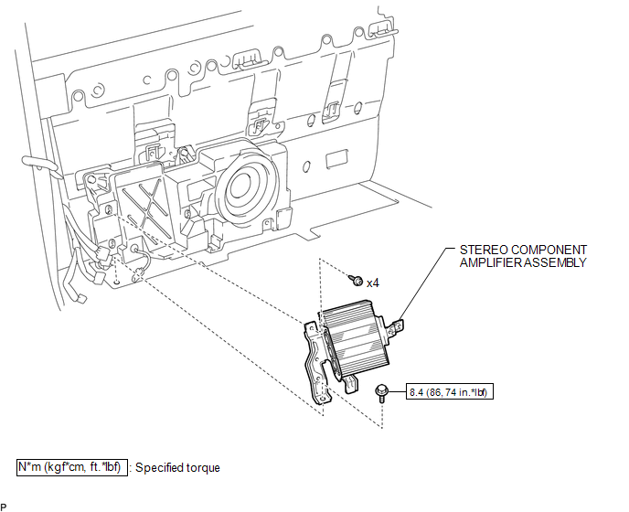
7. REMOVE STEREO COMPONENT AMPLIFIER ASSEMBLY
|
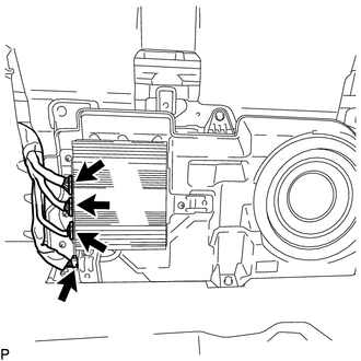
(a) Disconnect the 4 connectors. |
|
|
(b) Disengage the clamp. |
|
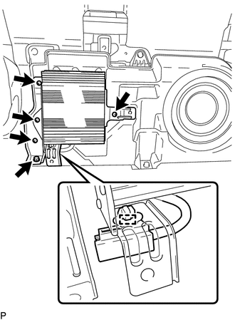
(c) Remove the bolt.
(d) Using a T20 "TORX" socket wrench, remove the 4 screws and stereo component amplifier assembly.
Installation
INSTALLATION
PROCEDURE
1. INSTALL STEREO COMPONENT AMPLIFIER ASSEMBLY
(a) Using a T20 "TORX" socket wrench, install the stereo component amplifier assembly with the 4 screws.
(b) Install the bolt.
Torque:
8.4 N·m {86 kgf·cm, 74 in·lbf}
(c) Engage the clamp.
(d) Connect the 4 connectors.
2. INSTALL LUGGAGE COMPARTMENT SIDE TRAY RH
(See page .gif) )
)
3. INSTALL LUGGAGE COMPARTMENT SIDE TRAY LH
(See page )
4. INSTALL REAR SEATBACK ASSEMBLY LH
(See page )
5. INSTALL REAR SEATBACK ASSEMBLY RH
(See page )
6. CONNECT CABLE TO NEGATIVE BATTERY TERMINAL
Torque:
5.4 N·m {55 kgf·cm, 48 in·lbf}
NOTICE:
When disconnecting the cable, some systems need to be initialized after the cable is reconnected.
Click here
 Steering Pad Switch
Components
COMPONENTS
ILLUSTRATION
*1
STEERING PAD SWITCH ASSEMBLY
-
-
Removal
REMOVAL
PROCEDURE
1. REMOVE STEERING PAD
(See page )
...

Other materials:
Open in Bus 2 Main Bus Line
DESCRIPTION
There may be an open circuit in one of the CAN main bus lines and/or a central
gateway ECU (network gateway ECU) branch lines when the resistance between terminals
18 (CA4H) and 17 (CA4L) of the central gateway ECU (network gateway ECU) is 70 Ω
or higher.
Detection It ...
Removal
REMOVAL
PROCEDURE
1. REMOVE FUEL TANK ASSEMBLY
Click here
2. DISCONNECT CHARCOAL CANISTER FUEL HOSE
(a) Loosen the hose clip and disconnect the charcoal canister fuel hose.
3. DISCONNECT FUEL TANK VENT HOSE
(a) Push the fuel tank vent hos ...
Ignition Switch
Components
COMPONENTS
ILLUSTRATION
Removal
REMOVAL
PROCEDURE
1. REMOVE LOWER STEERING COLUMN COVER
(a) Remove the 2 screws.
(b) Disengage the 2 claws and remove the lower steering column cover.
2. REMOVE IGNITION OR STARTER SWITCH ASSEMBLY
(a) Disconnect the connector.
(b) Disen ...
