Toyota Tacoma (2015-2018) Service Manual: Repair
REPAIR
PROCEDURE
1. REPAIR INTAKE VALVE SEATS
NOTICE:
- Repair the intake valve seat while checking the seating position.
- Keep the lip free of foreign matter.
|
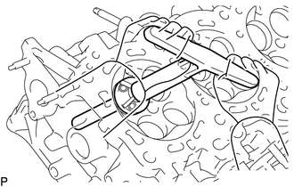
(a) Using a 45° cutter, resurface the valve seat so that the valve seat width is more than the specification. |
|
|
(b) Using 30° and 60° cutters, correct the valve seat so that the intake valve contacts the entire circumference of the seat. The contact should be in the center of the intake valve seat, and the intake valve seat width should be maintained within the specified range around the entire circumference of the intake valve seat. Text in Illustration
Standard width: 1.1 to 1.5 mm (0.0433 to 0.0591 in.) |
|

(c) Hand-lap the intake valve and intake valve seat with an abrasive compound.
(d) Check the intake valve seating position.
2. REPAIR EXHAUST VALVE SEATS
NOTICE:
- Repair the seat while checking the seating position.
- Keep the lip free of foreign matter.
|
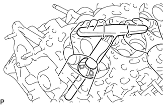
(a) Using a 45° cutter, resurface the valve seat so that the valve seat width is more than the specification. |
|
|
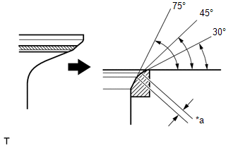
(b) Using 30° and 75° cutters, correct the exhaust valve seat so that the exhaust valve contacts the entire circumference of the seat. The contact should be in the center of the exhaust valve seat, and the exhaust valve seat width should be maintained within the specified range around the entire circumference of the exhaust valve seat. Text in Illustration
Standard width: 1.3 to 1.7 mm (0.0512 to 0.0669 in.) |
|
(c) Hand-lap the exhaust valve and exhaust valve seat with an abrasive compound.
(d) Check the exhaust valve seating position.
 Reassembly
REASSEMBLY
CAUTION / NOTICE / HINT
HINT:
Perform "Inspection After Repairs" after replacing the cylinder head sub-assembly
or cylinder head LH (See page ).
PROCEDURE
1. INSTALL SPARK ...

Other materials:
Installation
INSTALLATION
PROCEDURE
1. INSTALL REAR DIFFERENTIAL DRIVE PINION BEARING SPACER
(a) Install a new front differential drive pinion bearing spacer.
HINT:
Make sure the front differential drive pinion bearing spacer is installed correctly.
2. INSTALL DIFFERENTIAL OIL STORAGE RING
(a) Using a bra ...
Diagnosis System
DIAGNOSIS SYSTEM
1. DESCRIPTION
(a) When troubleshooting OBD II (On-Board Diagnostics) vehicles, an OBD II scan
tool (complying with SAE J1978) must be connected to the DLC3 (Data Link Connector
3) of the vehicle. Various data in the vehicle ECM (Engine Control Module) can be
then read.
(b) ...
Test Mode Procedure
TEST MODE PROCEDURE
1. TEST MODE (SIGNAL CHECK MODE) PROCEDURE
HINT:
When entering test mode (signal check mode), the tire pressure warning
ECU and receiver stores all the test mode (signal check mode) DTCs first.
After the tire pressure warning ECU and receiver completes the signa ...
