Toyota Tacoma (2015-2018) Service Manual: Tachometer Malfunction
DESCRIPTION
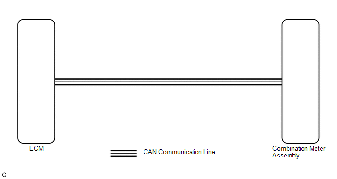
In this circuit, the meter CPU receives engine speed signals from the ECM using the CAN communication system (CAN V1 Bus). The meter CPU displays the engine speed calculated based on the data received from the ECM.
WIRING DIAGRAM
PROCEDURE
|
1. |
CHECK CAN COMMUNICATION SYSTEM |
(a) Check if a CAN communication DTC is output (See page
.gif) ).
).
|
Result |
Proceed to |
|---|---|
|
CAN communication DTC is not output |
A |
|
CAN communication DTC is output |
B |
| B | .gif) |
GO TO CAN COMMUNICATION SYSTEM |
|
.gif)
|
2. |
PERFORM ACTIVE TEST USING TECHSTREAM (TACHOMETER OPERATION) |
(a) Connect the Techstream to the DLC3.
(b) Turn the ignition switch to ON.
(c) Turn the Techstream on.
(d) Enter the following menus: Body Electrical / Combination Meter / Active Test.
(e) According to the display on the Techstream, perform the Active Test.
Combination Meter|
Tester Display |
Test Part |
Control Range |
Diagnostic Note |
|---|---|---|---|
|
TachoMeter Operation |
Tachometer |
OFF, 0, 1000, 2000, 3000, 4000, 5000, 6000, 7000 |
Operate with IG ON and the vehicle is stopped. |
OK:
Tachometer indication is normal.
| NG | |
REPLACE COMBINATION METER ASSEMBLY |
|
|
3. |
READ VALUE USING TECHSTREAM (ENGINE RPM) |
(a) Connect the Techstream to the DLC3.
(b) Start the engine.
(c) Turn the Techstream on.
(d) Enter the following menus: Body Electrical / Combination Meter / Data List.
(e) According to the display on the Techstream, read the Data List.
Combination Meter|
Tester Display |
Measurement Item/Range |
Normal Condition |
Diagnostic Note |
|---|---|---|---|
|
Engine Rpm |
Engine speed/ Min.: 0 rpm, Max.: 12750 rpm |
|
- |
OK:
Engine speed displayed on the Techstream is almost the same as the tachometer indication.
HINT:
Check the engine speed when the engine is fully warmed up, and the air conditioning and all electrical accessories are off.
| NG | |
REPLACE COMBINATION METER ASSEMBLY |
|
|
4. |
CHECK ENGINE CONTROL SYSTEM |
(a) Check if a engine control DTC is output.
- for 2TR-FE: (See page )
- for 2GR-FKS: (See page )
|
Result |
Proceed to |
|---|---|
|
Engine control DTC is not output |
A |
|
Engine control (for 2TR-FE) DTC is output |
B |
|
Engine control (for 2GR-FKS) DTC is output |
C |
| A | |
REPLACE COMBINATION METER ASSEMBLY |
| B | |
GO TO SFI SYSTEM (for 2TR-FE) |
| C | |
GO TO SFI SYSTEM (for 2GR-FKS) |
 Speedometer Malfunction
DESCRIPTION
The meter CPU receives vehicle speed signals from the skid control ECU via the
CAN communication system (CAN V1 Bus). The speed sensor detects the wheel speed
and sends the appropriat ...
 Engine Coolant Temperature Receiver Gauge Malfunction
DESCRIPTION
In this circuit, the meter CPU receives engine coolant temperature signals from
the ECM using the CAN communication system (CAN V1 Bus). The meter CPU displays
engine coolant temperat ...
Other materials:
Short to +B in Outer Mirror Indicator(Master) (C1AB0)
DESCRIPTION
This DTC is stored when the blind spot monitor sensor LH detects a +B short in
the blind spot monitor indicator LH.
DTC Code
DTC Detection Condition
Trouble Area
C1AB0
With the blind spot monitor main switch assembly (warni ...
Front Door Courtesy Switch
Inspection
INSPECTION
PROCEDURE
1. INSPECT FRONT DOOR COURTESY SWITCH
(a) Check the resistance.
(1) Measure the resistance using an ohmmeter, and check the results in accordance
with the value( s) in the table below.
Standard:
Tester Connection
Condition
...
Network Gateway Ecu
Components
COMPONENTS
ILLUSTRATION
Installation
INSTALLATION
PROCEDURE
1. INSTALL NETWORK GATEWAY ECU
(a) Install the network gateway ECU with the bolt.
Torque:
3.0 N·m {31 kgf·cm, 27 in·lbf}
(b) Connect the connector.
2. INSTALL LOWER INSTRUMENT PANEL ASSEMBLY
(See page )
R ...
