Toyota Tacoma (2015-2018) Service Manual: Removal
REMOVAL
PROCEDURE
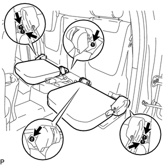
1. REMOVE REAR SEAT CUSHION ASSEMBLY
|
(a) Remove the 6 bolts and 2 rear seat cushion assemblies. |
|
2. REMOVE NO. 4 ROOM PARTITION COVER LH
.gif)
3. REMOVE NO. 4 ROOM PARTITION COVER RH
4. REMOVE NO. 3 ROOM PARTITION COVER
5. REMOVE BACK PANEL GARNISH HOLE PLUG
6. REMOVE BACK PANEL TRIM
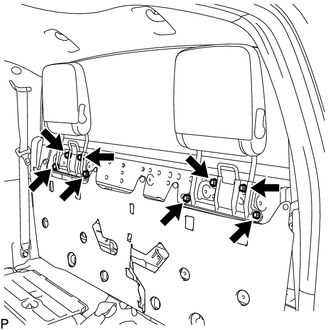
7. REMOVE REAR SEAT HEADREST ASSEMBLY
|
(a) Remove the 8 bolts and 2 rear seat headrest assemblies. |
|
8. REMOVE CHILD RESTRAINT SEAT ANCHOR BRACKET SUB-ASSEMBLY
HINT:
Use the same procedure for each side.
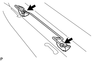
(a) Remove the 2 bolts and child restraint seat anchor bracket sub-assembly.
 Reassembly
REASSEMBLY
CAUTION / NOTICE / HINT
HINT:
The procedure described below is for the LH side. Use the same procedure for
both the LH and RH sides, unless otherwise specified.
PROCEDURE
1. INSTALL ...
 Installation
INSTALLATION
PROCEDURE
1. INSTALL CHILD RESTRAINT SEAT ANCHOR BRACKET SUB-ASSEMBLY
HINT:
Use the same procedure for the side.
(a) Install the child restraint seat anchor bracket sub-assembly with ...
Other materials:
Removal
REMOVAL
CAUTION / NOTICE / HINT
HINT:
Use the same procedure for both the RH and LH side.
The procedure described below is for the LH side.
PROCEDURE
1. REMOVE REAR ACCESS PANEL WEATHERSTRIP
2. REMOVE LAP BELT OUTER ANCHOR COVER
3. REMOVE ACCESS PANEL INSIDE HANDLE BEZ ...
Diagnostic Trouble Code Chart
DIAGNOSTIC TROUBLE CODE CHART
HINT:
If a trouble code is displayed during the DTC check, inspect the trouble area
for that code. For details of each code, refer to the relevant page listed under
respective "See page" in the DTC chart.
Tire Pressure Warning ECU and Receiver
...
Engine Coolant Temperature Receiver Gauge Malfunction
DESCRIPTION
In this circuit, the meter CPU receives engine coolant temperature signals from
the ECM using the CAN communication system (CAN V1 Bus). The meter CPU displays
engine coolant temperature that is calculated based on the data received from the
ECM.
WIRING DIAGRAM
CAUTION / NOTIC ...
