Toyota Tacoma (2015-2018) Service Manual: Reassembly
REASSEMBLY
CAUTION / NOTICE / HINT
HINT:
Perform "Inspection After Repairs" after replacing the cylinder head sub-assembly
or cylinder head LH (See page .gif) ).
).
PROCEDURE
1. INSTALL SPARK PLUG TUBE
NOTICE:
When using a new cylinder head, the spark plug tubes must be replaced.
|
(a) Apply adhesive onto the shaded area of a new spark plug tube. Text in Illustration
Adhesive: Toyota Genuine Adhesive 1324, Three Bond 1324 or equivalent. Standard application width: 1.0 to 3.0 mm (0.0394 to 0.118 in.) NOTICE:
|
|
|
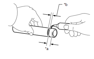
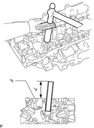
(b) Using a wooden block and hammer, tap in the spark plug tube to the specified protrusion height. Text in Illustration
Standard protrusion height: 75.65 mm (2.98 in.) NOTICE: To avoid tapping in the spark plug tube too far, measure the protrusion height while tapping it. |
|
2. INSTALL NO. 1 STRAIGHT SCREW PLUG
(a) Apply adhesive to the No. 1 straight screw plug of the cylinder head.
Adhesive:
Toyota Genuine Adhesive 1324, Three Bond 1324 or equivalent
(b) Using a 10 mm hexagon wrench, install 4 new gaskets and the 4 No. 1 straight screw plugs.
Torque:
44 N·m {449 kgf·cm, 32 ft·lbf}
3. INSTALL NO. 2 STRAIGHT SCREW PLUG
(a) Using a 14 mm hexagon wrench, install 2 new gaskets and the 2 No. 2 straight screw plugs.
Torque:
80 N·m {816 kgf·cm, 59 ft·lbf}
4. INSTALL NO. 3 STRAIGHT SCREW PLUG
(a) Using a 10 mm hexagon wrench, install 8 new gaskets and the 8 No. 3 straight screw plugs.
Torque:
44 N·m {449 kgf·cm, 32 ft·lbf}
5. INSTALL UNION
(a) Apply adhesive to the union of the cylinder head.
Adhesive:
Toyota Genuine Adhesive 1324, Three Bond 1324 or equivalent
(b) Using a union nut wrench (12 mm), install the union to the cylinder head as shown in the illustration.
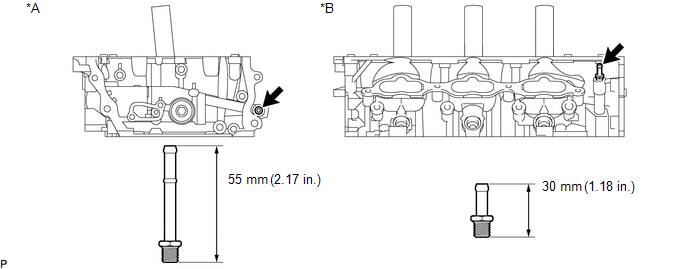 Text in Illustration
|
*A |
Bank 1 |
*B |
Bank 2 |
Torque:
15 N·m {150 kgf·cm, 11 ft·lbf}
6. INSTALL STUD BOLT
NOTICE:
If the stud bolt is deformed or the threads are damaged, replace it.
(a) Using E6 and E8 "TORX" socket wrenches, install the stud bolts.
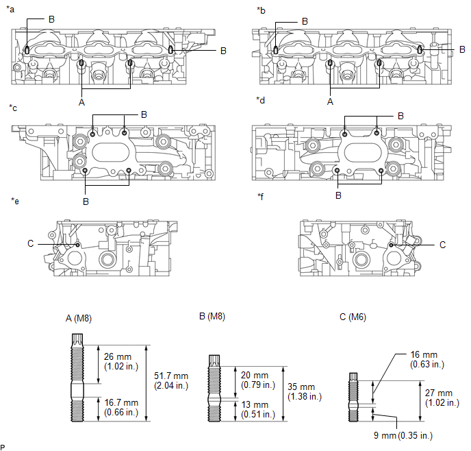 Text in Illustration
|
*a |
Intake Side RH |
*b |
Intake Side LH |
|
*c |
Exhaust Side RH |
*d |
Exhaust Side LH |
|
*e |
Rear Side RH |
*f |
Rear Side LH |
Torque:
for stud bolt A, B :
10 N·m {102 kgf·cm, 7 ft·lbf}
for stud bolt C :
4.0 N·m {41 kgf·cm, 35 in·lbf}
7. INSTALL VALVE SPRING SEAT
(a) Install the valve spring seats to the cylinder head.
8. INSTALL VALVE STEM OIL SEAL
|
(a) Apply a light coat of engine oil to new valve stem oil seals. Text in Illustration
NOTICE: Pay attention when installing the intake and exhaust valve stem oil seals. For example, installing the intake valve stem oil seal to the exhaust side or installing the exhaust valve stem oil seal to the intake side can cause installation problems later. HINT: The intake valve oil seals are black and the exhaust valve oil seals are gray. |
|
|
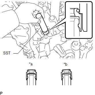
(b) Using SST, push in the oil seals. Text in Illustration
SST: 09201-41020 NOTICE: Failure to use SST will cause the seal to be damaged or improperly seated. |
|
9. INSTALL EXHAUST VALVE
|
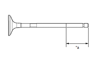
(a) Apply a sufficient coat of engine oil to the tip area of the exhaust valve shown in the illustration. Text in Illustration
|
|
(b) Install the exhaust valve, inner compression spring and valve spring retainer to the cylinder head.
NOTICE:
Install the same parts in the same combination to their original locations.
|
(c) Using SST, compress the inner compression spring and install the 2 valve spring retainer locks. SST: 09202-70020 09202-01010 09202-01020 SST: 09202-00021 |
|
.png)
(d) Using a plastic-faced hammer, lightly tap the valve stem tip to ensure a proper fit.
NOTICE:
Be careful not to damage the retainer.
10. INSTALL INTAKE VALVE
|
(a) Apply a sufficient coat of engine oil to the tip area of the intake valve shown in the illustration. Text in Illustration
|
|
(b) Install the intake valve, inner compression spring and valve spring retainer to the cylinder head.
NOTICE:
Install the same parts in the same combination to their original locations.
|
(c) Using SST, compress the inner compression spring and install the 2 valve spring retainer locks. SST: 09202-70020 09202-01010 09202-01020 SST: 09202-00021 |
|
.png)
(d) Using a plastic-faced hammer, lightly tap the valve stem tip to ensure a proper fit.
NOTICE:
Be careful not to damage the retainer.
 Replacement
REPLACEMENT
PROCEDURE
1. REPLACE INTAKE VALVE GUIDE BUSH
(a) Heat the cylinder head to 80 to 100°C (176 to 212°F).
(b) Place the cylinder head on wooden blocks.
(c) Using SST and a h ...
 Repair
REPAIR
PROCEDURE
1. REPAIR INTAKE VALVE SEATS
NOTICE:
Repair the intake valve seat while checking the seating position.
Keep the lip free of foreign matter.
(a) Us ...
Other materials:
Installation
INSTALLATION
PROCEDURE
1. INSTALL VANE PUMP
(a) Install the vane pump assembly with the 2 bolts.
Torque:
21 N·m {214 kgf·cm, 15 ft·lbf}
(b) Connect the oil pressure switch connector.
NOTICE:
Make sure that no oil adheres to the connector.
...
Rear Console Box
Components
COMPONENTS
ILLUSTRATION
ILLUSTRATION
Installation
INSTALLATION
PROCEDURE
1. INSTALL BOX BOTTOM MAT
(a) Engage the 10 guides and install the 2 box bottom mats.
2. INSTALL CONSOLE BOX PLATE
(a) Engage the 2 guides and install the console box plate.
(b) Install the 6 screw ...
Engine Immobiliser System Malfunction (B2799,B279986)
DESCRIPTION
This DTC is stored when one of the following occurs: 1) the ECM detects errors
in its own communication with the transponder key ECU assembly; 2) the ECM detects
errors in the communication lines; or 3) the ECU communication ID between the transponder
key ECU assembly and ECM is d ...
