Toyota Tacoma (2015-2018) Service Manual: Removal
REMOVAL
PROCEDURE
1. REMOVE AUTOMATIC TRANSMISSION ASSEMBLY (for Automatic Transmission)
|
Transmission |
See page |
|---|---|
|
AC60E |
|
|
AC60F |
|
2. REMOVE MANUAL TRANSMISSION ASSEMBLY (for Manual Transmission)
(See page .gif) )
)
3. REMOVE CLUTCH COVER ASSEMBLY (for Manual Transmission)
4. REMOVE CLUTCH DISC ASSEMBLY (for Manual Transmission)
5. REMOVE DRIVE PLATE AND RING GEAR SUB-ASSEMBLY (for Automatic Transmission)
6. REMOVE FLYWHEEL SUB-ASSEMBLY (for Manual Transmission)
7. REMOVE REAR ENGINE OIL SEAL
|
(a) Using a knife, cut off the lip of the rear engine oil seal. Text in Illustration
|
|
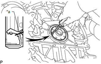
(b) Using a screwdriver, pry out the rear engine oil seal.
NOTICE:
Do not damage the surface of the rear engine oil seal press fit hole or crankshaft.
HINT:
Tape the screwdriver tip before use.
 Components
COMPONENTS
ILLUSTRATION
ILLUSTRATION
...
 Installation
INSTALLATION
PROCEDURE
1. INSTALL REAR ENGINE OIL SEAL
(a) Apply MP grease to the lip of a new rear engine oil seal.
NOTICE:
Keep the lip free of foreign matter.
(b) Using SST, tap in ...
Other materials:
Rear Leaf Spring
Components
COMPONENTS
ILLUSTRATION
Disassembly
DISASSEMBLY
PROCEDURE
1. REMOVE BUSH
(a) Fix the spring in a vise.
(b) Using a hack saw, cut both ends off the bushes.
(c) Using SST and a press, press out the 2 bushes.
SST: 09950-60010
09951-00350
SST: 09950-70010
...
Components
COMPONENTS
ILLUSTRATION
*1
RADIATOR GRILLE
-
-
ILLUSTRATION
*A
for Type A
*B
for Type B
*C
for Type C
-
-
*1
MILLIMET ...
Sending Malfunction (Navigation to APGS) (U0073,U0100,U0140,U0155)
DESCRIPTION
These DTCs are stored when a malfunction occurs in the CAN communication circuit.
DTC No.
DTC Detection Condition
Trouble Area
U0073
CAN bus connection error
CAN communication system
U0100
...
