Toyota Tacoma (2015-2018) Service Manual: Components
COMPONENTS
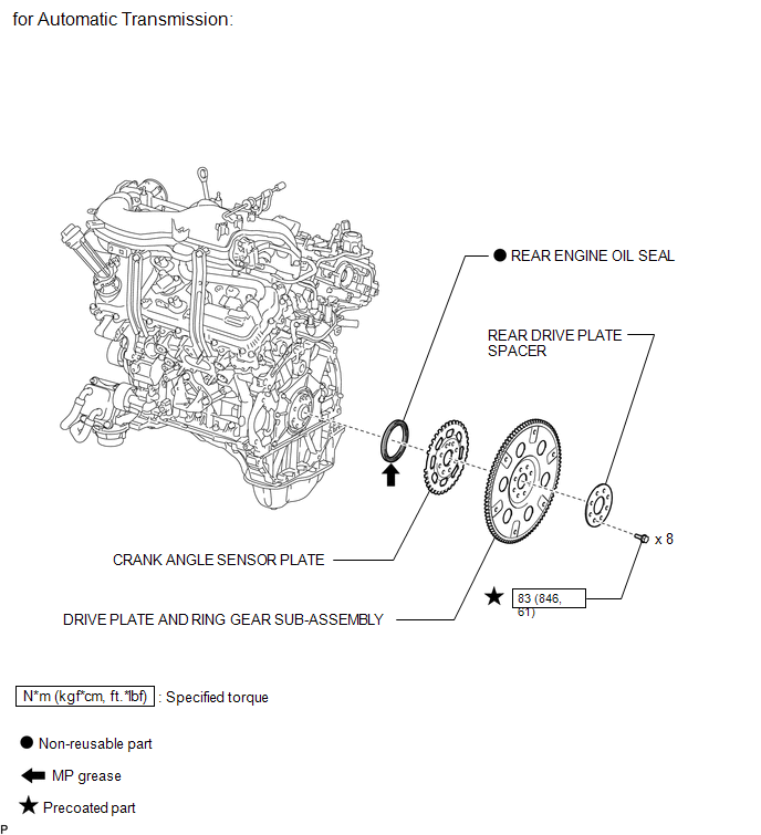
ILLUSTRATION
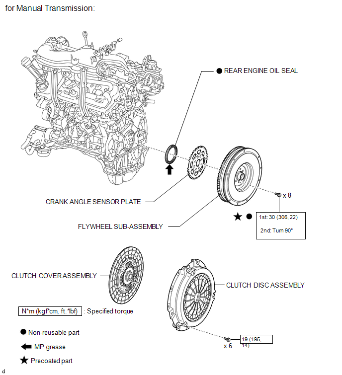
ILLUSTRATION

 Removal
REMOVAL
PROCEDURE
1. REMOVE AUTOMATIC TRANSMISSION ASSEMBLY (for Automatic Transmission)
Transmission
See page
AC60E
AC60F
...
Other materials:
Inspection
INSPECTION
PROCEDURE
1. INSPECT WINDSHIELD WIPER SWITCH ASSEMBLY
(a) Check the resistance.
Text in Illustration
*a
Component without harness connected
(Windshield Wiper Switch Assembly)
(1) Measure the resistance according ...
Steering Angle Sensor Output Malfunction (C1434)
DESCRIPTION
Steering angle sensor (spiral cable with sensor sub-assembly) signals are sent
to the skid control ECU (master cylinder solenoid) via the CAN communication system.
When there is a malfunction in the CAN communication system, it is detected by the
steering angle sensor (spiral cabl ...
Inspection
INSPECTION
PROCEDURE
1. REMOVE SPIRAL CABLE SUB-ASSEMBLY WITH SENSOR
(a) If there are any defects as mentioned below, replace the spiral cable sub-assembly
with a new one:
Scratches, cracks, dents or chips on the connector or the spiral cable sub-assembly.
(b) Inspect the spiral ca ...
