Toyota Tacoma (2015-2018) Service Manual: Removal
REMOVAL
PROCEDURE
1. REMOVE SLIDING ROOF SIDE GARNISH LH
(a) Fully open the sunshade trim sub-assembly.
|
(b) Remove the sliding roof side garnish LH. |
|

2. REMOVE SLIDING ROOF SIDE GARNISH RH
HINT:
Use the same procedure as for the LH side.
3. REMOVE SLIDING ROOF GLASS SUB-ASSEMBLY
|
(a) Using a T25 "TORX" socket wrench, remove the 4 screws and sliding roof glass sub-assembly. NOTICE: To prevent the sliding roof glass and sliding roof drive gear from being displaced, fully close the sliding roof glass (sliding roof drive cable), and then remove the sliding roof drive gear. HINT: The illustration shows the LH side. The vertical orientation of the RH side is opposite that of the image shown in the illustration. |
|
4. REMOVE CURTAIN SHIELD AIRBAG ASSEMBLY LH (for Double Cab)
(See page .gif) )
)
5. REMOVE CURTAIN SHIELD AIRBAG ASSEMBLY RH (for Double Cab)
HINT:
Use the same procedure as for the LH side.
6. REMOVE CURTAIN SHIELD AIRBAG ASSEMBLY LH (for Access Cab)
(See page
)
7. REMOVE CURTAIN SHIELD AIRBAG ASSEMBLY RH (for Access Cab)
HINT:
Use the same procedure as for the LH side.
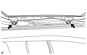
8. REMOVE ROOF PANEL SUPPORT LH (for Front Side)
|
(a) Remove the bolt, nut and roof panel support LH. |
|
9. REMOVE ROOF PANEL SUPPORT RH (for Front Side)
HINT:
Use the same procedure as for the LH side.
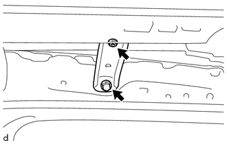
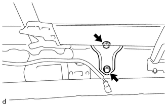
10. REMOVE ROOF PANEL SUPPORT LH (for Rear Side)
|
(a) Remove the 2 bolts and roof panel support LH. |
|
11. REMOVE ROOF PANEL SUPPORT RH (for Rear Side)
HINT:
Use the same procedure as for the LH side.
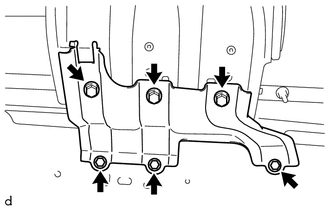
12. REMOVE SLIDING ROOF HOUSING BRACKET LH
|
(a) Remove the 6 bolts and sliding roof housing bracket LH. |
|
13. REMOVE SLIDING ROOF HOUSING BRACKET RH
HINT:
Use the same procedure as for the LH side.
14. REMOVE SLIDING ROOF HOUSING SUB-ASSEMBLY
|
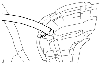
(a) Slide the clip and disconnect front side of the 2 sliding roof drain hoses. HINT: The illustration shows the LH side. The vertical orientation of the RH side is opposite that of the image shown in the illustration. |
|
|
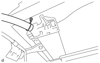
(b) Slide the clip and disconnect rear side of the 2 rear sliding roof drain hoses. HINT: The illustration shows the LH side. The vertical orientation of the RH side is opposite that of the image shown in the illustration. |
|
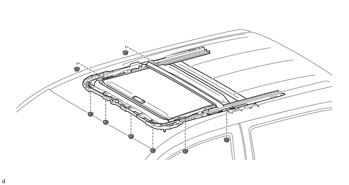
(c) Remove the 8 nuts and sliding roof housing sub-assembly.
15. REMOVE SLIDING ROOF WEATHERSTRIP
|
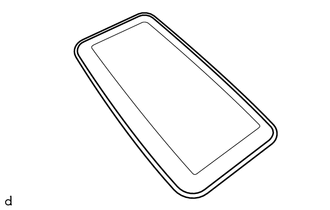
(a) Remove the sliding roof weatherstrip from the sliding roof glass. |
|
 Disassembly
DISASSEMBLY
PROCEDURE
1. REMOVE ROOM LIGHT BRACKET
(a) Disengage the guide to remove the room light bracket.
2. REMOVE SLIDING ROOF DRIVE GEAR ...
 Sliding Roof Switch Assembly
Components
COMPONENTS
ILLUSTRATION
Installation
INSTALLATION
PROCEDURE
1. INSTALL SLIDING ROOF SWITCH ASSEMBLY (ROOF CONSOLE BOX ASSEMBLY)
(a) Connect the connector.
(b) Engage the 4 cli ...
Other materials:
Reassembly
REASSEMBLY
PROCEDURE
1. INSTALL COMPRESSOR PICK UP SENSOR
(a) Install the compressor pick up sensor with the 3 screws.
(b) Engage the clamp.
2. INSTALL MAGNET CLUTCH ASSEMBLY
(a) Secure the cooler compressor assembly in a vise between ...
Power windows*
The power windows can be opened/closed using the following switches.
Driver’s power window switches
Closing
Opening
One-touch opening (driver’s window
only)*
*: To stop the window partway, operate the switch in the opposite direction.
Front and rear passenger’s power
window swi ...
Removal
REMOVAL
CAUTION / NOTICE / HINT
Text in Illustration
*a
Object Exceeding Weight Limit of Transmission Jack
Be sure to perform this procedure with several people as the rear differential
carrier assembly is very heavy.
Be sure to follow the procedure ...
