Toyota Tacoma (2015-2018) Service Manual: Disassembly
DISASSEMBLY
PROCEDURE
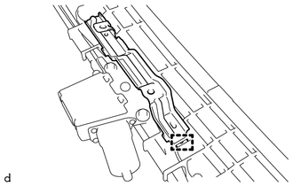
1. REMOVE ROOM LIGHT BRACKET
|
(a) Disengage the guide to remove the room light bracket. |
|
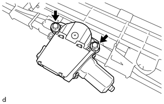
2. REMOVE SLIDING ROOF DRIVE GEAR SUB-ASSEMBLY
|
(a) Remove the 2 bolts and sliding roof drive gear sub-assembly. |
|
3. REMOVE SUNSHADE TRIM SUB-ASSEMBLY
|
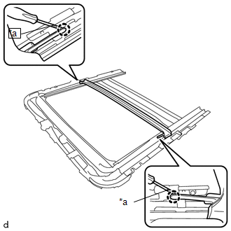
(a) Remove the screw. |
|
(b) Disengage the claw and 2 guides to remove the sliding roof drain hose joint LH as shown in the illustration.
|
(c) Remove the screw. |
|
(d) Disengage the claw and 2 guides to remove the sliding roof drain hose joint RH as shown in the illustration.
|
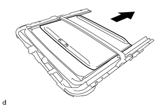
(e) Slide and remove the sunshade trim sub-assembly as shown in the illustration. |
|
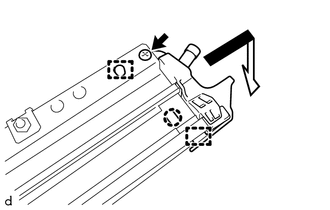
4. REMOVE ROOF DRIP CHANNEL
|
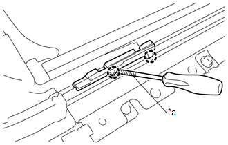
(a) Using a screwdriver with its tip wrapped in protective tape, disengage the 2 claws. Text in Illustration
|
|
|
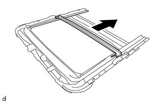
(b) Slide and remove the roof drip channel as shown in the illustration. |
|
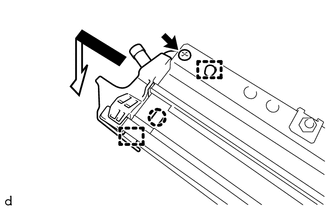
5. REMOVE SLIDING ROOF DRIVE CABLE SUB-ASSEMBLY LH
NOTICE:
Do not disassemble the sliding roof drive cable sub-assembly except when replacing it.
|
(a) Using a screwdriver with its tip wrapped in protective tape, disengage the 2 claws to remove the sliding roof guide block. Text in Illustration
|
|
(b) Remove the sliding roof drive cable sub-assembly LH.
6. REMOVE SLIDING ROOF DRIVE CABLE SUB-ASSEMBLY RH
HINT:
Use the same procedure as for the LH side.
 Components
COMPONENTS
ILLUSTRATION
ILLUSTRATION
ILLUSTRATION
...
 Removal
REMOVAL
PROCEDURE
1. REMOVE SLIDING ROOF SIDE GARNISH LH
(a) Fully open the sunshade trim sub-assembly.
(b) Remove the sliding roof side garnish LH.
...
Other materials:
Installation
INSTALLATION
CAUTION / NOTICE / HINT
CAUTION:
Some of these service operations affect the SRS airbag system. Read the precautionary
notices concerning the SRS airbag system before servicing.
Click here
PROCEDURE
1. INSTALL FRONT SEAT INNER BELT ASSEMBLY
(a) for Driver Side:
(1) Install t ...
Room Light Assembly
Components
COMPONENTS
ILLUSTRATION
Removal
REMOVAL
PROCEDURE
1. REMOVE NO. 1 ROOM LIGHT ASSEMBLY
(a) Using a screwdriver with its tip wrapped in protective tape, disengage
the 4 claws to remove the No. 1 room light lens.
Text in Illustration
*a
...
Removal
REMOVAL
PROCEDURE
1. PRECAUTION
NOTICE:
After turning the ignition switch off, waiting time may be required before disconnecting
the cable from the negative (-) battery terminal. Therefore, make sure to read the
disconnecting the cable from the negative (-) battery terminal notices before pr ...
