Toyota Tacoma (2015-2018) Service Manual: Sliding Roof Switch Assembly
Components
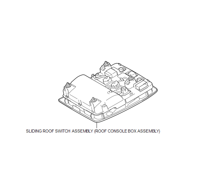
COMPONENTS
ILLUSTRATION
Installation
INSTALLATION
PROCEDURE
1. INSTALL SLIDING ROOF SWITCH ASSEMBLY (ROOF CONSOLE BOX ASSEMBLY)
(a) Connect the connector.
(b) Engage the 4 clips to install the sliding roof switch assembly (roof console box assembly).
Removal
REMOVAL
PROCEDURE
1. REMOVE SLIDING ROOF SWITCH ASSEMBLY (ROOF CONSOLE BOX ASSEMBLY)
|
(a) Using a moulding remover D, disengage the 4 clips to separate the sliding roof switch assembly (roof console box assembly). |
|
.png)
(b) Disconnect the connector to remove the sliding roof switch assembly (roof console box assembly).
 Removal
REMOVAL
PROCEDURE
1. REMOVE SLIDING ROOF SIDE GARNISH LH
(a) Fully open the sunshade trim sub-assembly.
(b) Remove the sliding roof side garnish LH.
...

Other materials:
Pressure Control Solenoid "A" Electrical (Shift Solenoid Valve SL1) (P0748)
DESCRIPTION
Changing from 1st to 6th is performed by the ECM turning shift solenoid valves
SL1, SL2, SL3 and SL4 on and off. If an open or short circuit occurs in any of the
shift solenoid valves, the ECM controls the remaining normal shift solenoid valves
to allow the vehicle to be operated ...
Installation
INSTALLATION
PROCEDURE
1. INSTALL TRANSMISSION FLOOR SHIFT ASSEMBLY
(a) Install the transmission floor shift assembly to the vehicle body with the
4 bolts.
Torque:
14 N·m {143 kgf·cm, 10 ft·lbf}
(b) Attach the 4 clamps to connect the wire harness to the transmission floor
shift assembl ...
SM Solenoid Circuit (C1225-C1228,C1468,C1469,C146A,C146B)
DESCRIPTION
The solenoid goes on when signals are received from the skid control ECU (master
cylinder solenoid) and controls the pressure action on the wheel cylinders thus
controlling the braking force.
DTC No.
DTC Detecting Conditions
Trouble Areas
...
