Toyota Tacoma (2015-2018) Service Manual: Removal
REMOVAL
CAUTION / NOTICE / HINT
 Text in Illustration
|
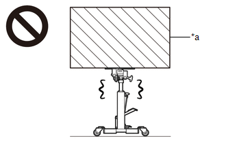
*a |
Object Exceeding Weight Limit of Transmission Jack |
- Be sure to perform this procedure with several people as the rear differential carrier assembly is very heavy.
- Be sure to follow the procedure described in the repair manual, or the transmission jack may suddenly drop or a part may fall.
HINT:
The following procedures are for BD20 (w/o Differential Lock).
PROCEDURE
1. REMOVE REAR WHEELS
2. REMOVE REAR PROPELLER SHAFT ASSEMBLY (for 2WD)
(See page .gif) )
)
3. REMOVE REAR PROPELLER SHAFT ASSEMBLY (for 4WD)
(See page )
4. DRAIN DIFFERENTIAL OIL
(See page )
5. REMOVE REAR AXLE SHAFT WITH BACKING PLATE LH
(See page )
6. REMOVE REAR AXLE SHAFT WITH BACKING PLATE RH
HINT:
Use the same procedure described for the LH side.
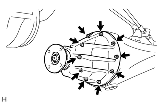
7. REMOVE REAR DIFFERENTIAL CARRIER ASSEMBLY
|
(a) Remove the 10 nuts, 10 washers and rear differential carrier assembly. CAUTION: The rear differential carrier assembly is a heavy component. Make sure that it is supported securely. NOTICE:
|
|
8. REMOVE REAR DIFFERENTIAL CARRIER GASKET
 Components
COMPONENTS
ILLUSTRATION
HINT:
The following specifications are for BD20D (w/o Differential Lock). BD20D differentials
are equipped with M8 rear differential carrier to rear axel housing fasteners ...
 Installation
INSTALLATION
CAUTION / NOTICE / HINT
HINT:
The following procedures are for BD20 (w/o Differential Lock).
PROCEDURE
1. INSTALL REAR DIFFERENTIAL CARRIER ASSEMBLY
(a) Clean the contact surfaces o ...
Other materials:
System Diagram
SYSTEM DIAGRAM
Transmitting ECU (Transmitter)
Receiving ECU
Signal
Communication Method
Skid control ECU (Brake actuator assembly)
Steering angle sensor (Spiral cable with sensor sub-assembly)
Steering angl ...
Entry Exterior Alarm and Answer-back Buzzer do not Sound
DESCRIPTION
The smart key system (for Entry Function) uses the wireless door lock buzzer
to perform various vehicle exterior warnings. When the conditions of each warning
are met, the certification ECU (smart key ECU assembly) sends a buzzer activation
request signal to the main body ECU (mul ...
Removal
REMOVAL
CAUTION / NOTICE / HINT
HINT:
Use the same procedure for both the LH and RH sides.
The procedure described below is for the LH side.
PROCEDURE
1. REMOVE FRONT BUMPER ASSEMBLY
(See page
)
2. REMOVE HEADLIGHT ASSEMBLY
(a) Apply protective tape around the headlight ...
