Toyota Tacoma (2015-2018) Service Manual: Removal
REMOVAL
PROCEDURE
1. REMOVE PROPELLER SHAFT WITH CENTER BEARING ASSEMBLY
|
(a) Place matchmarks on the propeller shaft flange and differential flange. Text in Illustration
|
|
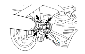
(b) for Differential Type BD20:
(1) Remove the 4 nuts, 4 bolts and 4 washers to disconnect the propeller shaft.
(c) for Differential Type BD22:
(1) Remove the 4 nuts and 4 washers to disconnect the propeller shaft.
|
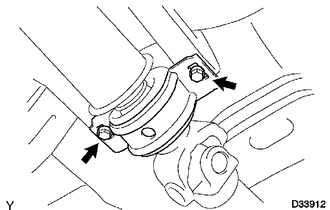
(d) Remove the 2 bolts to separate the center No. 2 support bearing assembly from the frame crossmember. |
|
|
(e) Pull out the propeller shaft. |
|
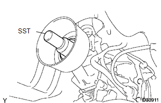
(f) Insert SST to the extension housing to prevent oil leakage.
SST: 09325-40010
 Components
COMPONENTS
ILLUSTRATION
...
 Disassembly
DISASSEMBLY
PROCEDURE
1. INSPECT PROPELLER SHAFT UNIVERSAL JOINT SPIDER BEARING
(a) Check the spider bearings for wear and damage.
(b) Check each spider bearings axial play by turning the yoke whi ...
Other materials:
Data List / Active Test
DATA LIST / ACTIVE TEST
1. READ DATA LIST
HINT:
Using the Techstream to read the Data List allows the values or states of switches,
sensors, actuators and other items to be read without removing any parts. This non-intrusive
inspection can be very useful because intermittent conditions or sig ...
Crankshaft Position Sensor
Components
COMPONENTS
ILLUSTRATION
Installation
INSTALLATION
PROCEDURE
1. INSTALL CRANKSHAFT POSITION SENSOR
(a) Apply a light coat of engine oil to the O-ring of the crankshaft position
sensor.
NOTICE:
When reusing the crankshaft position sensor, inspect the O-ring.
...
Installation
INSTALLATION
PROCEDURE
1. INSTALL REAR SEATBACK HINGE SUB-ASSEMBLY
(a) Install the rear seatback hinge sub-assembly with the 2 bolts.
Torque:
30 N·m {306 kgf·cm, 22 ft·lbf}
2. INSTALL REAR SEATBACK ASSEMBLY
(a) Install the rear seatback assembly with the 2 bolts.
Torque:
37 N·m {377 k ...
