Toyota Tacoma (2015-2018) Service Manual: Open in Outer Mirror Indicator(Master) (C1AB4)
DESCRIPTION
This DTC is stored when the blind spot monitor sensor LH detects an open in the blind spot monitor indicator LH.
|
DTC Code |
DTC Detection Condition |
Trouble Area |
|---|---|---|
|
C1AB4 |
With the blind spot monitor main switch assembly (warning canceling switch assembly) on, the current flowing to the indicator is below a specified value when indicator operation voltage is sent to the indicator. |
|
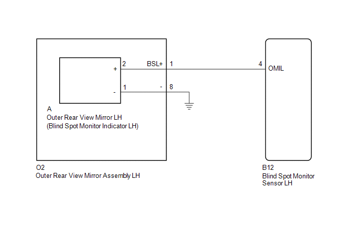
WIRING DIAGRAM
CAUTION / NOTICE / HINT
NOTICE:
When checking for DTCs, make sure that the blind spot monitor main switch assembly (warning canceling switch assembly) is on.
PROCEDURE
|
1. |
CHECK DTC |
(a) Clear the DTCs (See page .gif) ).
).
(b) Recheck for DTCs and check if the same DTC is output again (See page
).
OK:
No DTCs are output.
| OK | .gif) |
USE SIMULATION METHOD TO CHECK |
|
.gif)
|
2. |
CHECK HARNESS AND CONNECTOR (OUTER REAR VIEW MIRROR ASSEMBLY LH - BLIND SPOT MONITOR SENSOR LH AND BODY GROUND) |
(a) Disconnect the B12 blind spot monitor sensor LH connector.
(b) Disconnect the O2 outer rear view mirror assembly LH connector.
(c) Measure the resistance according to the value(s) in the table below.
Standard Resistance:
|
Tester Connection |
Condition |
Specified Condition |
|---|---|---|
|
B12-4 (OMIL) - O2-1 (BSL+) |
Always |
Below 1 Ω |
|
O2-8 - Body ground |
Always |
Below 1 Ω |
| NG | |
REPAIR OR REPLACE HARNESS OR CONNECTOR |
|
|
3. |
INSPECT OUTER REAR VIEW MIRROR ASSEMBLY LH |
(a) Remove the outer rear view mirror assembly LH (See page
).
(b) Remove the outer rear view mirror LH (See page
).
(c) Measure the resistance according to the value(s) in the table below.
Standard Resistance:
|
Tester Connection |
Condition |
Specified Condition |
|---|---|---|
|
O2-1 (BSL+) - A-2 (+) |
Always |
Below 1 Ω |
|
O2-8 - A-1 (-) |
Always |
Below 1 Ω |
| NG | |
REPLACE OUTER REAR VIEW MIRROR ASSEMBLY LH |
|
|
4. |
CHECK OUTER REAR VIEW MIRROR LH |
(a) Replace the outer rear view mirror LH with a new or normally functioning
one (See page ).
(b) Clear the DTCs (See page ).
(c) Recheck for DTCs and check if the same DTC is output again (See page
).
OK:
No DTCs are output.
| OK | |
END (OUTER REAR VIEW MIRROR LH WAS DEFECTIVE) |
| NG | |
REPLACE BLIND SPOT MONITOR SENSOR LH |
 Blind Spot Monitor Master Module (C1AB6)
DESCRIPTION
This DTC is stored when the blind spot monitor sensor LH detects an internal
malfunction.
DTC Code
DTC Detection Condition
Trouble Area
...
 Short to GND in Outer Mirror Indicator(Master) (C1AB2)
DESCRIPTION
This DTC is stored when the blind spot monitor sensor LH detects a ground short
in the blind spot monitor indicator LH.
DTC Code
DTC Detection Condition
...
Other materials:
Side Airbag Sensor LH Circuit Malfunction (B1625/22)
DESCRIPTION
The side airbag sensor assembly LH consists of parts such as the safing sensor,
the diagnostic circuit and the lateral deceleration sensor.
When the airbag sensor assembly receives signals from the lateral deceleration
sensor, it determines whether or not the SRS should be activate ...
Brake Warning Light Remains ON
DESCRIPTION
The BRAKE warning light comes on when brake fluid is insufficient, the parking
brake is applied or the EBD is defective.
WIRING DIAGRAM
CAUTION / NOTICE / HINT
NOTICE:
When replacing the skid control ECU (master cylinder solenoid), perform
calibration (See page
...
Terminals Of Ecu
TERMINALS OF ECU
1. CHECK MAIN BODY ECU (MULTIPLEX NETWORK BODY ECU)
(a) Disconnect the 1D and 1F driver side junction block connectors.
(b) Measure the voltage and resistance according to the value(s) in the table
below.
HINT:
Measure the values on the wire harness side with the connectors ...
