Toyota Tacoma (2015-2018) Service Manual: Components
COMPONENTS
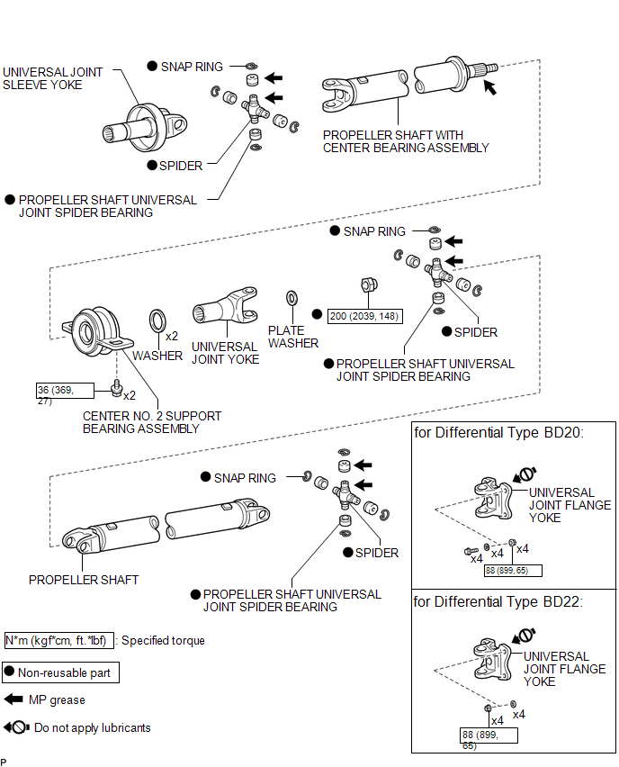
ILLUSTRATION

 Removal
REMOVAL
PROCEDURE
1. REMOVE PROPELLER SHAFT WITH CENTER BEARING ASSEMBLY
(a) Place matchmarks on the propeller shaft flange and differential flange.
Text in Illustration
...
Other materials:
Vehicle Speed Sensor Circuit (C1AA3)
DESCRIPTION
The forward recognition camera receives vehicle speed signals from the skid control
ECU. If the skid control ECU receives a vehicle speed sensor malfunction signal,
it informs the forward recognition camera via CAN communication, and DTC C1AA3 is
stored.
DTC No.
...
Disassembly
DISASSEMBLY
PROCEDURE
1. REMOVE CONNECTOR COVER
(a) Disengage the 2 clips to remove the connector cover.
2. REMOVE REAR BUMPER PAD SUB-ASSEMBLY
(a) Separate the 2 license plate light assemblies as shown in the illustration.
...
Sound Signal Circuit between Radio Receiver and Stereo Jack Adapter
DESCRIPTION
The No. 1 stereo jack adapter assembly sends the sound signal from an external
device to the navigation receiver assembly via this circuit.
If there is an open or short in the circuit, sound cannot be heard from the speakers
even if there is no malfunction in the stereo component a ...
