Toyota Tacoma (2015-2018) Service Manual: Disassembly
DISASSEMBLY
PROCEDURE
1. INSPECT PROPELLER SHAFT UNIVERSAL JOINT SPIDER BEARING
(a) Check the spider bearings for wear and damage.
(b) Check each spider bearings axial play by turning the yoke while holding the shaft tightly.
Maximum bearing axial play:
0 to 0.05 mm (0 to 0.00197 in.)
If the bearing axial play is greater than the maximum, replace the spider bearing.
2. REMOVE PROPELLER SHAFT UNIVERSAL JOINT SPIDER BEARING
|
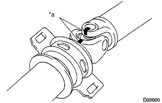
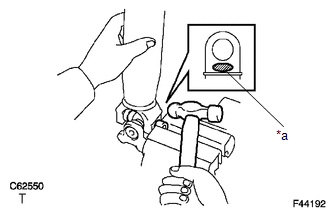
(a) Place matchmarks on the propeller shaft and universal joint yoke. Text in Illustration
|
|
|
(b) Using a brass bar and hammer, slightly tap in the spider bearing outer races. |
|
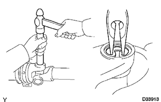
(c) Using needle-nose pliers, remove the 4 snap rings from the grooves.
|
(d) Clamp the propeller shaft in a vise between aluminum plates. NOTICE: Do not overtighten the vise. |
|
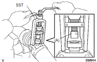
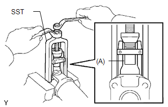
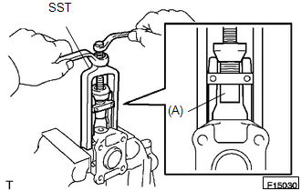
(e) Using SST, push the spider bearing out of the propeller shaft.
SST: 09332-25010
HINT:
Sufficiently raise the part indicated by (A) so that it does not come into contact with the spider bearing.
|
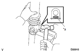
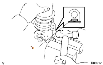
(f) Clamp the pushed out spider bearing outer race in a vise and tap the propeller shaft to remove the spider bearing. Text in Illustration
NOTICE: Do not tap the shaft. HINT: Remove the spider bearing from the opposite side of the spider using the same procedure. |
|
(g) Separate the propeller with center No. 2 support bearing assembly from the propeller shaft assembly.
|
(h) Reinstall the 2 removed spider bearings to the spider and clamp the spider bearings in a vise. NOTICE: Do not overtighten the vise. |
|
(i) Using SST, push the spider bearing out of the yoke.
SST: 09332-25010
HINT:
Sufficiently raise the part indicated by (A) so that it does not come into contact with the spider bearing.
|
(j) Clamp the pushed out spider bearing outer race in a vise and tap off the yoke with a hammer. Text in Illustration
|
|
(k) Remove the spider.
3. REMOVE PROPELLER SHAFT UNIVERSAL JOINT SPIDER BEARING
|
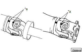
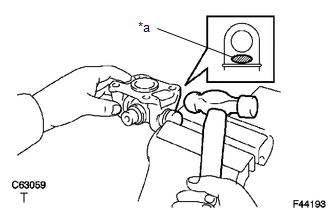
(a) Place matchmarks on the flange yoke and sleeve yoke. Text in Illustration
|
|
|
(b) Using a brass bar and hammer, slightly tap in the spider bearing outer races. |
|
.png)
(c) Using needle-nose pliers, remove the 4 snap rings from the grooves.
|
(d) Clamp the propeller shaft in a vise between aluminum plates. NOTICE: Do not overtighten the vise. |
|
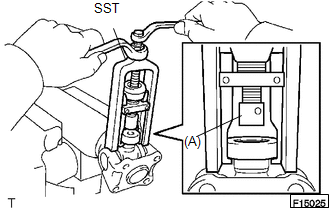
(e) Using SST, push the spider bearing out of the propeller shaft.
SST: 09332-25010
HINT:
Sufficiently raise the part indicated by (A) so that it does not come into contact with the spider bearing.
|
(f) Clamp the pushed out spider bearing outer race in a vise and tap the propeller shaft to remove the spider bearing. Text in Illustration
NOTICE: Do not tap the shaft tube. HINT: Remove the spider bearing from the opposite side of the spider using the same procedure. |
|
(g) Separate the flange yoke and spider from the propeller shaft.
|
(h) Reinstall the 2 removed spider bearings to the spider and clamp the spider bearings in a vise. NOTICE: Do not overtighten the vise. |
|
(i) Using SST, push the spider bearing out of the yoke.
SST: 09332-25010
HINT:
Sufficiently raise the part indicated by (A) so that it does not come into contact with the spider bearing.
|
(j) Clamp the pushed out spider bearing outer race in a vise and tap off the yoke with a hammer. Text in Illustration
|
|
(k) Remove the spider.
4. REMOVE CENTER NO. 2 SUPPORT BEARING ASSEMBLY
(a) Fix the yoke at the center No. 2 support bearing assembly section in a vise between aluminum plates.
NOTICE:
Do not overtighten the vise.
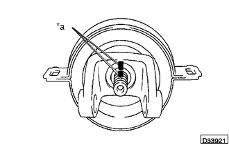
(b) Using a chisel and a hammer, loosen the staked part of the lock nut.
(c) Remove the lock nut and plate washer.
|
(d) Place matchmarks on the universal joint yoke and propeller shaft with center bearing assembly. Text in Illustration
|
|
(e) Using a brass bar and hammer, remove the universal joint yoke, washer and center No. 2 support bearing assembly from the propeller shaft with center bearing assembly.
 Removal
REMOVAL
PROCEDURE
1. REMOVE PROPELLER SHAFT WITH CENTER BEARING ASSEMBLY
(a) Place matchmarks on the propeller shaft flange and differential flange.
Text in Illustration
...
 Inspection
INSPECTION
PROCEDURE
1. INSPECT PROPELLER SHAFT WITH CENTER BEARING ASSEMBLY
(a) Using a dial indicator, check the propeller shaft with center bearing assembly
runout.
Maximum runout:
0.6 mm ...
Other materials:
Installation
INSTALLATION
CAUTION / NOTICE / HINT
HINT:
Use the same procedure for the RH and LH sides.
The procedure listed below is for the LH side.
PROCEDURE
1. INSTALL REAR SPEAKER ASSEMBLY
(a) Install the rear speaker assembly with the 3 screws.
NOTICE:
Do not touch the cone part o ...
Radar Cruise Control Presence Determination Malfunction (Engine / HV) (C1A52)
DESCRIPTION
DTC C1A52 is stored when the ECM cannot recognize the millimeter wave radar sensor
assembly.
DTC No.
Detection Item
DTC Detection Condition
Trouble Area
MIL
C1A52
Radar Cruise Control Presence Determin ...
Acceleration Sensor Stuck Malfunction (C1232,C1243,C1245)
DESCRIPTION
The skid control ECU (brake actuator assembly) receives signals from the yaw
rate and acceleration sensor (airbag sensor assembly) via the CAN communication
system.
The airbag sensor assembly has a built-in acceleration sensor and detects the
vehicle condition.
If there is troub ...
