Toyota Tacoma (2015-2018) Service Manual: Removal
REMOVAL
PROCEDURE
1. PRECAUTION
NOTICE:
After turning the ignition switch off, waiting time may be required before disconnecting the cable from the negative (-) battery terminal. Therefore, make sure to read the disconnecting the cable from the negative (-) battery terminal notices before proceeding with work.
Click here .gif)
2. DISCONNECT CABLE FROM NEGATIVE BATTERY TERMINAL
NOTICE:
When disconnecting the cable, some systems need to be initialized after the cable is reconnected.
Click here
3. REMOVE FRONT WHEELS
4. REMOVE NO. 2 ENGINE UNDER COVER SUB-ASSEMBLY (w/ Off Road Package)
5. REMOVE NO. 1 ENGINE UNDER COVER SUB-ASSEMBLY
6. DRAIN DIFFERENTIAL OIL
Click here
7. REMOVE FRONT PROPELLER SHAFT ASSEMBLY
Click here
8. REMOVE FRONT AXLE SHAFT LH NUT
Click here
9. REMOVE FRONT AXLE SHAFT RH NUT
HINT:
Use the same procedure as for the LH side.
10. SEPARATE FRONT STABILIZER LINK ASSEMBLY LH
Click here
11. SEPARATE FRONT STABILIZER LINK ASSEMBLY RH
HINT:
Use the same procedure as for the LH side.
12. SEPARATE FRONT SPEED SENSOR LH
Click here
13. SEPARATE FRONT SPEED SENSOR RH
HINT:
Use the same procedure as for the LH side.
14. SEPARATE TIE ROD END SUB-ASSEMBLY LH
Click here
15. SEPARATE TIE ROD END SUB-ASSEMBLY RH
HINT:
Use the same procedure as for the LH side.
16. SEPARATE FRONT SUSPENSION LOWER ARM LH
Click here
17. SEPARATE FRONT SUSPENSION LOWER ARM RH
HINT:
Use the same procedure as for the LH side.
18. REMOVE FRONT DRIVE SHAFT ASSEMBLY LH
Click here
19. REMOVE FRONT DRIVE SHAFT ASSEMBLY RH
HINT:
Use the same procedure as for the LH side.
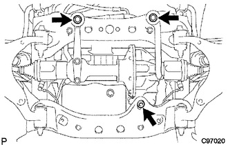
20. REMOVE FRONT DIFFERENTIAL CARRIER ASSEMBLY
(a) Remove the bolt and separate the front differential breather tube bracket.
(b) Support the front differential with a jack.
(c) Remove the front differential mount nut No. 1.
(d) Remove the 2 front mounting bolts and 2 nuts.
(e) Disconnect the actuator hose and connector.
(f) Disconnect the differential oil temperature sensor connector and clip.
(g) Remove the bolt and disconnect the bracket.
(h) Lower the jack and remove the front differential assembly.
(i) Remove the 2 bolts and No. 3 front differential support.
(j) Remove the 5 bolts and 2 front differential supports.
 Components
COMPONENTS
ILLUSTRATION
ILLUSTRATION
ILLUSTRATION
ILLUSTRATION
...
 Installation
INSTALLATION
PROCEDURE
1. INSTALL FRONT DIFFERENTIAL CARRIER ASSEMBLY
(a) Connect the actuator hose and connector.
(b) Install the No. 1 mounting support with the 3 bolts.
Torque:
186 N·m {1 ...
Other materials:
Removal
REMOVAL
CAUTION / NOTICE / HINT
Text in Illustration
*a
Object Exceeding Weight Limit of Transmission Jack
Be sure to perform this procedure with several people as the rear differential
carrier assembly is very heavy.
Be sure to follow the procedure ...
Removal
REMOVAL
CAUTION / NOTICE / HINT
HINT:
Use the same procedure for the RH side and LH side.
The following procedure is for the LH side.
PROCEDURE
1. PRECAUTION
NOTICE:
After turning the ignition switch off, waiting time may be required before disconnecting
the cable from the ...
Parts Location
PARTS LOCATION
ILLUSTRATION
ILLUSTRATION
ILLUSTRATION
ILLUSTRATION
...
