Toyota Tacoma (2015-2018) Service Manual: Rear Speed Sensor
Removal
REMOVAL
PROCEDURE
1. PRECAUTION
NOTICE:
After turning the ignition switch off, waiting time may be required before disconnecting the cable from the negative (-) battery terminal.
Therefore, make sure to read the disconnecting the cable from the negative (-) battery terminal notices before proceeding with work.
Click here .gif)
2. DISCONNECT CABLE FROM NEGATIVE BATTERY TERMINAL
NOTICE:
When disconnecting the cable, some systems need to be initialized after the cable is reconnected.
Click here
3. REMOVE REAR SPEED SENSOR
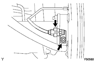
(a) Disconnect the speed sensor connector.
(b) Remove the nut and speed sensor rear.
NOTICE:
- Do not attach any foreign matter to the sensor tip.
- Ensure that no foreign matter enters the sensor installation hole.
Installation
INSTALLATION
PROCEDURE
1. INSTALL REAR SPEED SENSOR
.png)
(a) Install the rear speed sensor with the nut.
Torque:
8.0 N·m {82 kgf·cm, 71 in·lbf}
NOTICE:
Make sure that the sensor tip is clean.
(b) Connect the speed sensor connector.
2. CONNECT CABLE TO NEGATIVE BATTERY TERMINAL
Torque:
5.4 N·m {55 kgf·cm, 48 in·lbf}
NOTICE:
When disconnecting the cable, some systems need to be initialized after the cable is reconnected.
Click here .gif)
3. CHECK VSC SENSOR SIGNAL (for Hydraulic Brake Booster)
Click here
4. CHECK VSC SENSOR SIGNAL (for Vacuum Brake Booster)
Click here
 Multi-terrain Select Switch
Components
COMPONENTS
ILLUSTRATION
Removal
REMOVAL
PROCEDURE
1. REMOVE MULTI-TERRAIN SELECT SWITCH (DRIVE MONITOR SWITCH)
(a) Disengage the 2 claws to remove the multi-terrain ...

Other materials:
Unable to Unlock Steering Wheel (Engine cannot Start)
DESCRIPTION
The steering lock actuator assembly activates the steering lock motor and moves
the lock bar into the steering column to lock the steering.
The steering may not unlock when the lock bar gets stuck in the lock hole of
the steering column. In this case, if the engine switch is turned ...
Speaker Output Short (B15C3)
DESCRIPTION
This DTC is stored when a malfunction occurs in the speakers.
DTC No.
DTC Detection Condition
Trouble Area
B15C3
A short is detected in the speaker output circuit.
Harness or connector
Speaker
...
AUTO LSD Indicator Light does not Come ON
DESCRIPTION
The AUTO LSD does not operate even if the VSC OFF switch is pressed under the
following conditions:
The brake system is faulty.
The temperature inside the hydraulic brake booster increases and the
AUTO LSD operation is suspended.
WIRING DIAGRAM
CAUTION / NOTI ...
