Toyota Tacoma (2015-2018) Service Manual: Intake Air Control Valve Actuator(for Acis)
Components
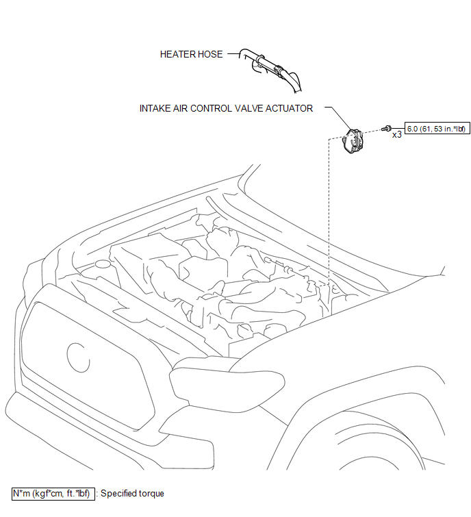
COMPONENTS
ILLUSTRATION
Inspection
INSPECTION
PROCEDURE
1. INSPECT INTAKE AIR CONTROL VALVE ACTUATOR
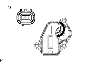
(a) Check the operate.
|
(1) Apply battery voltage to the connector, and check the operation of the intake air control valve actuator gear. Text in Illustration
OK:
NOTICE: Apply battery voltage for 10 seconds or less each time the inspection is performed. If the result is not as specified, replace the intake air control valve actuator. |
|
On-vehicle Inspection
ON-VEHICLE INSPECTION
PROCEDURE
1. INSPECT INTAKE AIR CONTROL VALVE ACTUATOR
(a) Remove the intake air control valve actuator.
(See page .gif) )
)
(b) Connect the connector to the intake air control valve actuator.
(c) Connect the Techstream to the DLC3.
(d) Turn the ignition switch ON and turn the Techstream on.
(e) Enter the following menus: Powertrain / Engine / Active Test / Control the ACIS VSV Motor Duty Ratio.
|
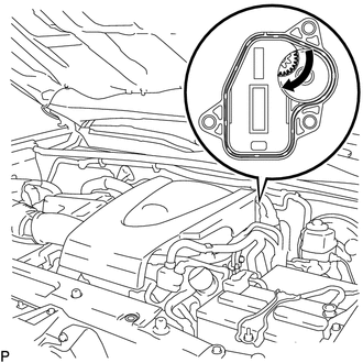
(f) Rotate the intake air control valve actuator gear clockwise and check that it turns freely. If the operation is not as specified, replace the intake air control valve actuator. |
|
(g) Disconnect the connector from the intake air control valve actuator.
(h) Install the intake air control valve actuator.
(See page )
Removal
REMOVAL
PROCEDURE
1. REMOVE INTAKE AIR CONTROL VALVE ACTUATOR
|
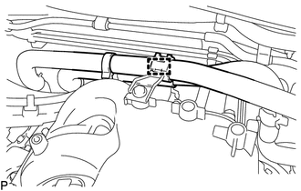
(a) Disengage the clamp to separate the heater hose from the intake air surge tank assembly. |
|
(b) Disconnect the connector from the intake air control valve actuator.
|
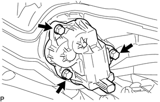
(c) Remove the 3 bolts and intake air control valve actuator from the intake air surge tank assembly. |
|
Installation
INSTALLATION
PROCEDURE
1. INSTALL INTAKE AIR CONTROL VALVE ACTUATOR
(a) Install the intake air control valve actuator to the intake air surge tank assembly with the 3 bolts.
Torque:
6.0 N·m {61 kgf·cm, 53 in·lbf}
(b) Connect the connector to the intake air control valve actuator.
(c) Engage the clamp to install the heater hose to the intake air surge tank assembly.
 2gr-fks Intake
...
 Intake Manifold
...
Other materials:
Diagnosis System
DIAGNOSIS SYSTEM
1. CHECK DLC3
(a) The vehicle's ECU uses the ISO 9141-2 for communication protocol. The terminal
arrangement of the DLC3 complies with SAE J1962 and matches the ISO 15765-4 format.
Symbols (Terminal No.)
Terminal Description
Condition
...
Installation
INSTALLATION
PROCEDURE
1. INSTALL POWER STEERING LINK
(a) Insert the power steering link into the vehicle in the order shown in the
illustration.
Install in this Direction (1)
Install in this Direction (2)
(b) Using SST, inst ...
Key Cannot be Registered
DESCRIPTION
A maximum of 5 master key ID codes can be registered.
WIRING DIAGRAM
Refer to "B2780" (See page )
CAUTION / NOTICE / HINT
NOTICE:
If the transponder key ECU assembly is replaced, refer to Registration (See page
).
PROCEDURE
1.
CHECK REGISTRATIO ...
