Toyota Tacoma (2015-2018) Service Manual: Reassembly
REASSEMBLY
PROCEDURE
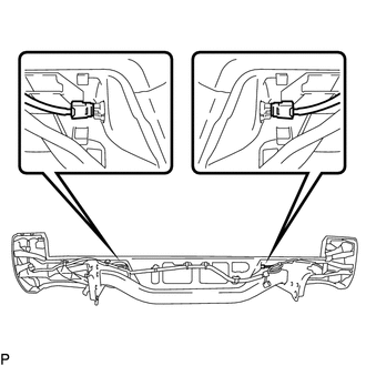
1. INSTALL REAR BUMPER SIDE STAY LH
|
(a) Install the rear bumper side stay LH with the 2 bolts. Torque: 30 N·m {306 kgf·cm, 22 ft·lbf} |
|
.png)
2. INSTALL REAR BUMPER SIDE STAY RH
HINT:
Use the same procedure as for the LH side.
3. INSTALL NO. 6 FLOOR WIRE
|
(a) Engage the wire harness clamps to install the No. 6 floor wire. Text in Illustration
|
|
.png)
(b) Install 2 new adhesive tapes.
4. INSTALL BLIND SPOT MONITOR SENSOR LH (w/ Blind Spot Monitor)
|
(a) Install the blind spot monitor sensor LH with the 3 nuts. Torque: 9.0 N·m {92 kgf·cm, 80 in·lbf} |
|
.png)
(b) Connect the connector.
5. INSTALL BLIND SPOT MONITOR SENSOR RH (w/ Blind Spot Monitor)
HINT:
Use the same procedure as for the LH side.
6. INSTALL NO. 1 ULTRASONIC SENSOR (w/ Clearance Sonar System)
.gif)
7. INSTALL REAR BUMPER EXTENSION LH
(a) w/ Clearance Sonar System:
|
(1) Connect the connector. Text in Illustration
|
|
.png)
(b) Install the rear bumper extension LH.
(c) Install the clamp.
(d) Install the 5 clips.
8. INSTALL REAR BUMPER EXTENSION RH
HINT:
Use the same procedure as for the LH side.
9. INSTALL REAR BUMPER PLATE
(a) Engage the 6 guides to install the rear bumper plate.
.png) Text in Illustration
Text in Illustration
|
*a |
Wire Harness Clamp |
*b |
Guide |
(b) Install the 10 bolts.
Torque:
30 N·m {306 kgf·cm, 22 ft·lbf}
(c) Engage the wire harness clamps.
10. INSTALL NO. 1 ULTRASONIC SENSOR (w/ Clearance Sonar System)
11. INSTALL REAR BUMPER PAD SUB-ASSEMBLY
|
(a) Engage the 2 claws to install the license plate light lens. HINT: Use the same procedure for the RH side and LH side. |
|
.png)
(b) w/ Clearance Sonar System:
(1) Connect the 2 connectors.
.png)
(2) Engage the 14 claws to install the rear bumper pad sub-assembly.
(3) Install the 3 clips.
(c) w/o Clearance Sonar System:
(1) Engage the 14 claws to install the rear bumper pad sub-assembly.
.png)
(2) Install the 3 clips.
|
(d) Connect the connector to install the license plate light. HINT: Use the same procedure for the RH side and LH side. |
|
.png)
|
(e) Install the 2 license plate light assemblies. |
|
12. INSTALL REAR BUMPER HOLE COVER
|
(a) Engage the 2 claws to install the rear bumper hole cover. |
|
.png)
 Installation
INSTALLATION
PROCEDURE
1. INSTALL REAR BUMPER ASSEMBLY
(a) Using an engine lifter or equivalent, engage the 2 pins to install the rear
bumper assembly.
Text in Illustration
*a
...

Other materials:
Inspection
INSPECTION
PROCEDURE
1. INSPECT WATER INLET WITH THERMOSTAT SUB-ASSEMBLY
HINT:
The valve opening temperature is inscribed on the water inlet with thermostat
sub-assembly.
(a) Immerse the thermostat in the water, then heat the water gradually.
CAUTION:
Do not your hands into the wa ...
Installation
INSTALLATION
PROCEDURE
1. INSTALL PARK/NEUTRAL POSITION SWITCH
HINT:
Make sure that the manual valve lever shaft has not been rotated prior to installing
the park/neutral position switch as the detent spring may become detached from the
manual valve lever shaft.
(a) Clean the bolt and bolt ...
Short in Driver Side Squib 2nd Step Circuit (B1810/53-B1813/53)
DESCRIPTION
The driver side squib 2nd step circuit consists of the airbag sensor assembly,
the spiral cable with sensor sub-assembly and the horn button assembly.
The circuit signals the SRS to deploy when airbag deployment conditions are met.
These DTCs are set when a malfunction is detected i ...
