Toyota Tacoma (2015-2018) Service Manual: Installation
INSTALLATION
PROCEDURE
1. INSTALL PARK/NEUTRAL POSITION SWITCH
HINT:
Make sure that the manual valve lever shaft has not been rotated prior to installing the park/neutral position switch as the detent spring may become detached from the manual valve lever shaft.
(a) Clean the bolt and bolt hole.
(b) Apply adhesive to 2 or 3 threads on the end of the bolt.
Adhesive:
Toyota Genuine Adhesive 1344, Three Bond 1344 or equivalent
(c) Temporarily install the park/neutral position switch to the automatic transmission assembly with the bolt.
HINT:
Tighten the bolt to the specified torque when adjusting the park/neutral position switch.
(d) Install a new lock washer and nut to the park/neutral position switch.
Torque:
6.9 N·m {70 kgf·cm, 61 in·lbf}
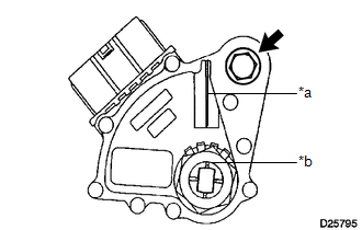
(e) Move the shift lever to N.
|
(f) Align the neutral basic line with the groove as shown in the illustration, and tighten the bolt. Text in Illustration
Torque: 13 N·m {130 kgf·cm, 9 ft·lbf} |
|
(g) Using a screwdriver, bend the tabs of the lock washer.
NOTICE:
- Be careful not to damage the park/neutral position switch.
- Bend at least 2 of the lock washer tabs.
HINT:
Tape the screwdriver tip before use.
(h) Connect the park/neutral position switch connector.
2. INSTALL WATER BY-PASS PIPE (for 2GR-FKS)
(a) Install the water by-pass pipe to the automatic transmission assembly with the 2 bolts.
Torque:
21 N·m {214 kgf·cm, 15 ft·lbf}
3. INSTALL TRANSMISSION INSULATOR RH (for 2GR-FKS)
.gif)
4. INSTALL TRANSMISSION INSULATOR RH (for 2TR-FE)
5. INSPECT PARK/NEUTRAL POSITION SWITCH
 Inspection
INSPECTION
PROCEDURE
1. INSPECT PARK/NEUTRAL POSITION SWITCH
(a) Measure the resistance according to the value(s) in the table below.
Text in Illustration
*a
...
 Pattern Select Switch
Components
COMPONENTS
ILLUSTRATION
Removal
REMOVAL
PROCEDURE
1. REMOVE INSTRUMENT PANEL LOWER CENTER FINISH PANEL
(See page )
2. REMOVE PATTERN SELECT SWITCH ASSEMBLY
(a) D ...
Other materials:
Stop Light Switch
Components
COMPONENTS
ILLUSTRATION
Inspection
INSPECTION
PROCEDURE
1. INSPECT STOP LIGHT SWITCH
(a) Check the resistance.
(1) Measure the resistance using an ohmmeter, and check the results in accordance
with the value(s) in the table below.
Standard:
Tester Connectio ...
Fail-safe Chart
FAIL-SAFE CHART
If any of the following DTCs are stored, the ECM enters fail-safe mode to allow
the vehicle to be driven temporarily.
DTC
Fail-safe Operation
Fail-safe Deactivation Condition
P161A87
Generator command is maintained
...
Fail-safe Chart
FAIL-SAFE CHART
1. FAIL SAFE OPERATION
If there is a problem with any sensor signals or hydraulic brake booster
systems, the skid control ECU prohibits the power supply to the actuator
in the hydraulic brake booster and informs the ECM of VSC system failure.
The hydraulic brake b ...
