Toyota Tacoma (2015-2018) Service Manual: Rear Differential Lock Control SW Stuck ON (P17CC)
DESCRIPTION
This DTC is output when a malfunction of the differential lock switch is detected.
|
DTC No. |
Detection Item |
DTC Detection Condition |
Trouble Area |
|---|---|---|---|
|
P17CC |
Rear Differential Lock Control SW Stuck ON |
|
|
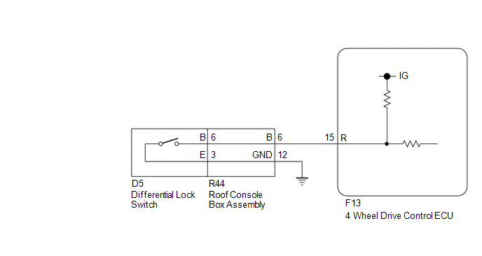
WIRING DIAGRAM
PROCEDURE
|
1. |
CHECK HARNESS AND CONNECTOR (4 WHEEL DRIVE CONTROL ECU - DIFFERENTIAL LOCK SWITCH) |
(a) Disconnect the F13 4 wheel drive control ECU connector.
(b) Disconnect the D5 differential lock switch connector.
(c) Measure the resistance according to the value(s) in the table below.
Standard Resistance:
|
Tester Connection |
Condition |
Specified Condition |
|---|---|---|
|
F13-15 (R) or D5-6 (B) - Body ground |
Always |
10 kΩ or higher |
| NG | .gif) |
REPAIR OR REPLACE HARNESS OR CONNECTOR |
|
.gif)
|
2. |
INSPECT ROOF CONSOLE BOX ASSEMBLY |
(a) Remove the roof console box assembly.
- for Double Cab: (See page
.gif) ).
). - for Access Cab: (See page
).
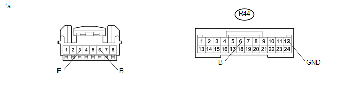 Text in Illustration
|
*a |
Component without harness connected (Roof Console Box Assembly) |
- |
- |
(b) Measure the resistance according the value(s) in the table below.
Standard Resistance:
|
Tester Connection |
Condition |
Specified Condition |
|---|---|---|
|
R44-6 (B) - 6 (B) |
Always |
Below 1 Ω |
|
R44-12 (GND)- 3 (E) |
Always |
Below 1 Ω |
|
Result |
Proceed to |
|---|---|
|
OK |
A |
|
NG (for Double Cab) |
B |
|
NG (for Access Cab) |
C |
| B | |
REPLACE ROOF CONSOLE BOX ASSEMBLY |
| C | |
REPLACE ROOF CONSOLE BOX ASSEMBLY |
|
|
3. |
INSPECT DIFFERENTIAL LOCK SWITCH |
(a) Disconnect the D5 differential lock switch connector.
|
(b) Measure the resistance according to the value(s) in the table below. Standard Resistance:
|
|
| OK | |
REPLACE 4 WHEEL DRIVE CONTROL ECU |
| NG | |
REPLACE DIFFERENTIAL LOCK SWITCH |
 Rear Differential Lock Solenoid Circuit High (P17C1)
DESCRIPTION
This DTC is output when a malfunction is detected due to a battery short occurring
in the differential lock coil drive circuit of the rear differential.
DTC No.
D ...
 Rear Differential Lock Position SW Stuck OFF (P17BB)
DESCRIPTION
This DTC is output when an OFF malfunction of the differential lock indicator
switch is detected.
DTC No.
Detection Item
DTC Detection Condition
...
Other materials:
Installation
INSTALLATION
PROCEDURE
1. INSTALL FRONT DISC
(a) Align the matchmarks of the front disc and the front axle hub and
install the front disc.
Text in Illustration
*a
Matchmark
HINT:
When replacing the disc with a new one, se ...
Check Bus 3 Line for Short to GND
DESCRIPTION
There may be a short circuit between one of the CAN bus lines and GND when there
is no resistance between terminal 6 (CA3H) of the central gateway ECU (network gateway
ECU) and terminal 4 (CG) of the DLC3, or terminal 21 (CA3L) of the central gateway
ECU (network gateway ECU) and ...
Registered Device cannot be Deleted
PROCEDURE
1.
DELETE OPERATION
(a) Check if a registered portable player can be deleted normally.
OK:
Registered portable player can be deleted normally.
OK
END
NG
PROCEED TO NEXT SUSPECTED AREA SHOWN IN PROBLEM SYM ...
