Toyota Tacoma (2015-2018) Service Manual: Installation
INSTALLATION
CAUTION / NOTICE / HINT
HINT:
- Use the same procedure for both the RH and LH sides.
- The procedure described below is for the LH side.
PROCEDURE
1. INSTALL CURTAIN SHIELD AIRBAG ASSEMBLY
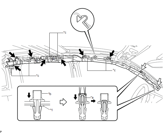
(a) Insert the 6 hooks, install 7 new bolts, 2 new clips (A) with pins and 2 new spacers, and engage 2 clips (B) to install the curtain shield airbag assembly.
 Text in Illustration
|
*1 |
Spacer |
- |
- |
|
*a |
Pin |
*b |
Clip (A) |
|
*c |
Hook |
- |
- |
Torque:
12.5 N·m {127 kgf·cm, 9 ft·lbf}
NOTICE:
Do not twist the curtain shield airbag assembly.
|
(b) Connect the airbag connector to the curtain shield airbag assembly. NOTICE: When handling the airbag connector, take care not to damage the airbag wire harness. |
|
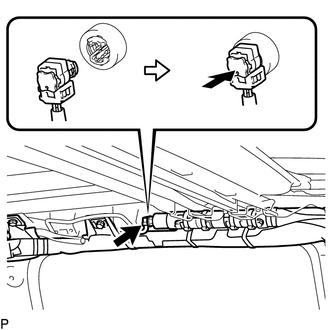
(c) Push in the airbag connector lock to install the airbag connector.
2. INSTALL ROOF HEADLINING ASSEMBLY
Click here .gif)
3. CONNECT CABLE TO NEGATIVE BATTERY TERMINAL
Torque:
5.4 N·m {55 kgf·cm, 48 in·lbf}
NOTICE:
When disconnecting the cable, some systems need to be initialized after the cable is reconnected.
Click here
4. INSPECT SRS WARNING LIGHT
Click here
 Disposal
DISPOSAL
CAUTION / NOTICE / HINT
CAUTION:
Before performing pre-disposal deployment of any SRS part, review and closely
follow all applicable environmental and hazardous material regulations. Pre ...

Other materials:
Inspection
INSPECTION
PROCEDURE
1. INSPECT FRONT NO. 2 SPEAKER ASSEMBLY
(a) When there is a malfunction such as noise from a speaker or no sound at all,
replace the speaker with a new one and check that the malfunction disappears.
OK:
Malfunction disappears.
HINT:
Connect the connectors to th ...
How To Proceed With Troubleshooting
CAUTION / NOTICE / HINT
HINT:
Use the following procedure to troubleshoot the navigation system.
*: Use the Techstream.
PROCEDURE
1.
VEHICLE BROUGHT TO WORKSHOP
NEXT
2 ...
On-vehicle Inspection
ON-VEHICLE INSPECTION
PROCEDURE
1. INSPECT REFRIGERANT PRESSURE
(a) This method uses a refrigerant recovery unit set to locate problem areas.
Read the refrigerant pressure when the test conditions are established.
Test conditions:
Temperature at the air inlet with the air recirculation ...
