Toyota Tacoma (2015-2018) Service Manual: Rear Differential Lock Solenoid Circuit High (P17C1)
DESCRIPTION
This DTC is output when a malfunction is detected due to a battery short occurring in the differential lock coil drive circuit of the rear differential.
|
DTC No. |
Detection Item |
DTC Detection Condition |
Trouble Area |
|---|---|---|---|
|
P17C1 |
Rear Differential Lock Solenoid Circuit High |
|
|
WIRING DIAGRAM
Refer to DTC P17C0 (See page .gif) ).
).
PROCEDURE
|
1. |
CHECK DIFFERENTIAL LOCK COIL |
(a) Disconnect the 4 wheel drive control ECU connector.
|
(b) Measure the voltage according to the value(s) in the table below. Standard Voltage:
|
|
| OK | .gif) |
REPLACE 4 WHEEL DRIVE CONTROL ECU |
|
.gif)
|
2. |
CHECK HARNESS AND CONNECTOR (4 WHEEL DRIVE CONTROL ECU - DIFFERENTIAL LOCK COIL) |
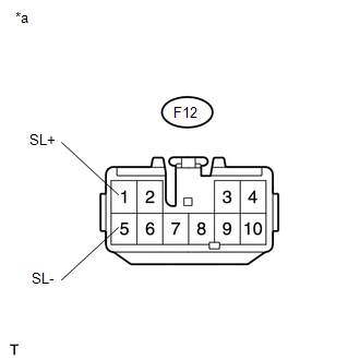
(a) Disconnect the F12 4 wheel drive control ECU connector.
(b) Disconnect the D28 differential lock coil connector.
(c) Measure the voltage according to the value(s) in the table below.
Standard Voltage:
|
Tester Connection |
Switch Condition |
Specified Condition |
|---|---|---|
|
F12-1 (SL+) or D28-2 (SL+) - Body ground |
Ignition switch ON |
Below 1 V |
|
F12-5 (SL-) or D28-1 (SL-) - Body ground |
Ignition switch ON |
Below 1 V |
| OK | |
REPLACE DIFFERENTIAL LOCK COIL |
| NG | |
REPAIR OR REPLACE HARNESS OR CONNECTOR |
 Rear Differential Lock Solenoid Circuit Low (P17C0)
DESCRIPTION
This DTC is output when a malfunction is detected due to a short to ground occurring
in the differential lock coil drive circuit of the rear differential.
DTC No.
...
 Rear Differential Lock Control SW Stuck ON (P17CC)
DESCRIPTION
This DTC is output when a malfunction of the differential lock switch is detected.
DTC No.
Detection Item
DTC Detection Condition
Trouble Area ...
Other materials:
Customize Parameters
CUSTOMIZE PARAMETERS
1. LANE DEPARTURE ALERT SYSTEM
Click here
2. INTUITIVE PARKING ASSIST SYSTEM
Click here
3. PRE-COLLISION SYSTEM
Click here
4. SEAT BELT WARNING SYSTEM
Click here
5. AIR CONDITIONING SYSTEM (for Automatic Air Conditioning System)
Click here
6. THEFT DETERRENT ...
Panel Switches do not Function
PROCEDURE
1.
CHECK PANEL SWITCH
(a) Check for foreign matter around the switches that might prevent operation.
OK:
No foreign matter is found.
NG
REMOVE ANY FOREIGN MATTER FOUND
OK
...
Monitor Drive Pattern
MONITOR DRIVE PATTERN
1. TEST MONITOR DRIVE PATTERN FOR ECT
CAUTION:
Perform this drive pattern on a level surface and strictly observe the posted
speed limits and traffic laws while driving.
HINT:
Performing this drive pattern is one method to simulate the ECM (ECT) malfunction
detection c ...
