Toyota Tacoma (2015-2018) Service Manual: Rear Body Side Panel Protector
Components
COMPONENTS
ILLUSTRATION
ILLUSTRATION
Installation
INSTALLATION
CAUTION / NOTICE / HINT
HINT:
- Use the same procedure for the RH side and LH side.
- The following procedure is for the LH side.
PROCEDURE
1. INSTALL REAR BODY SIDE PANEL PROTECTOR
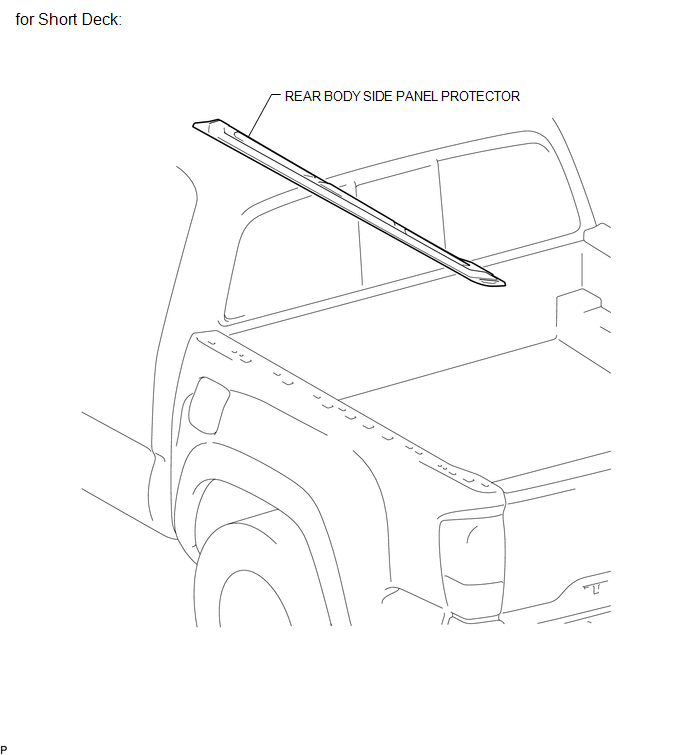
(a) for Short Deck:
(1) Engage the 2 guides and 14 claws to install the rear body side protector.
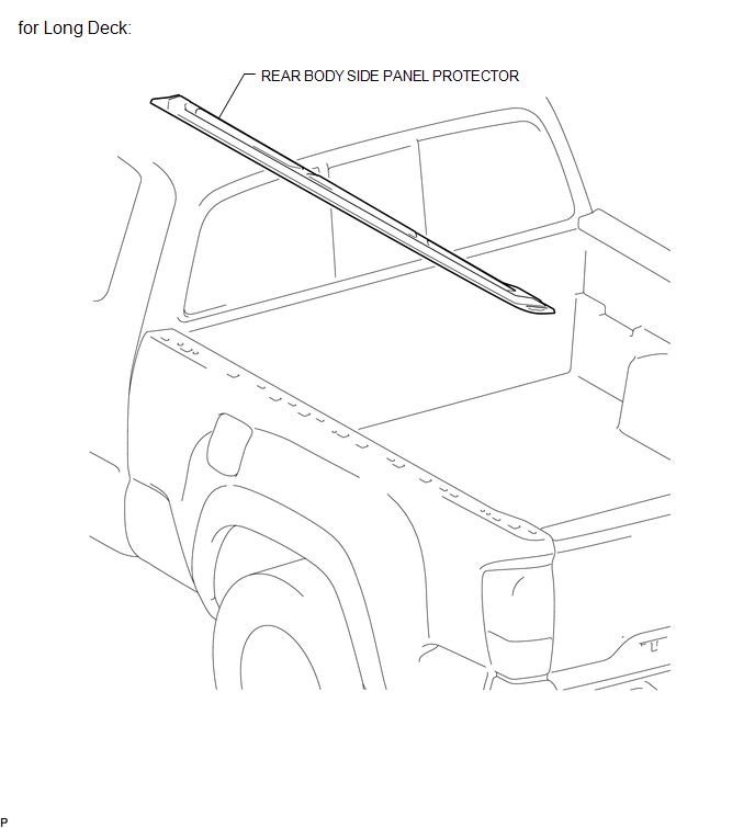
(b) for Long Deck:
(1) Engage the 2 guides and 19 claws to install the rear body side protector.
(c) Remove the protective tape.
2. INSTALL TOP COVER SUB-ASSEMBLY (w/ Tonneau Cover)
(See page .gif) )
)
Removal
REMOVAL
CAUTION / NOTICE / HINT
HINT:
- Use the same procedure for the RH side and LH side.
- The following procedure is for the LH side.
PROCEDURE
1. REMOVE TOP COVER SUB-ASSEMBLY (w/ Tonneau Cover)
(See page .gif) )
)
2. REMOVE REAR BODY SIDE PANEL PROTECTOR
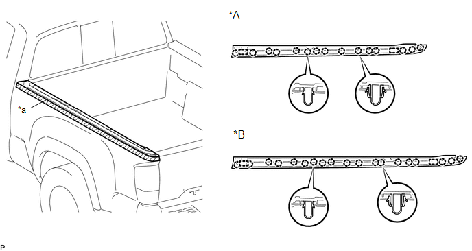
(a) Put protective tape around the rear body side panel protector.
 Text in Illustration
|
*A |
for Short Deck |
*B |
for Long Deck |
|
*a |
Protective Tape |
- |
- |
(b) for Short Deck:
(1) Disengage the 15 claws and 2 guides to remove the rear body side panel protector.
(c) for Long Deck:
(1) Disengage the 19 claws and 2 guides to remove the rear body side panel protector.
 Reassembly
REASSEMBLY
PROCEDURE
1. INSTALL RADIATOR GRILLE MOULDING
(a) Engage the 8 claws to install the radiator grille moulding.
(b) Install the 8 ...

Other materials:
Fail-safe Chart
FAIL-SAFE CHART
1. FAIL-SAFE OPERATION AND DEACTIVATION CONDITION
DIFFERENTIAL SYSTEM (w/ Differential Lock)
DTC No.
Fail-safe Operation
Fail-safe Deactivation Condition
U0122
All switching prohibited
When rear differential is locked ...
Disassembly
DISASSEMBLY
PROCEDURE
1. INSPECT COUNTERSHAFT REVERSE GEAR THRUST CLEARANCE
(a) Using a dial indicator, measure the countershaft reverse gear thrust
clearance.
Standard clearance:
0.150 to 0.300 mm (0.0060 to 0.0118 in.)
If the clearance is outside the specification, repl ...
Dtc Check / Clear
DTC CHECK / CLEAR
HINT:
When using the Techstream with the engine switch off to troubleshoot:
Connect the Techstream to the DLC3 and turn a courtesy light switch on and
off at 1.5 second intervals until communication between the Techstream and
vehicle begins.
Refer to the T ...
