Toyota Tacoma (2015-2018) Service Manual: System Diagram
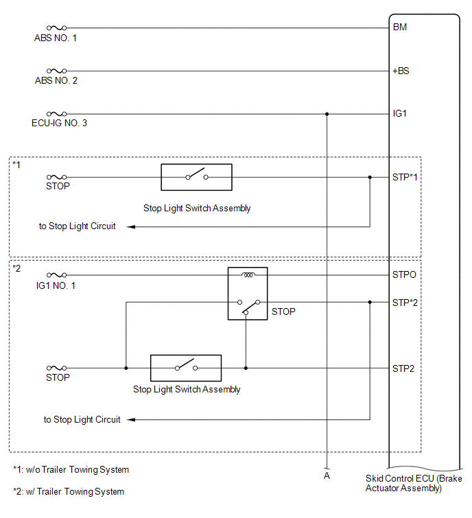
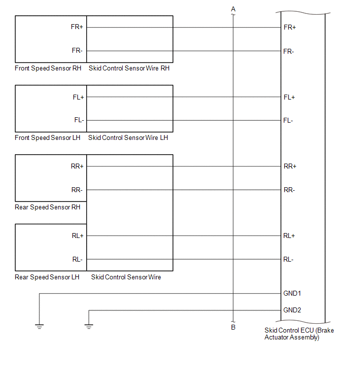
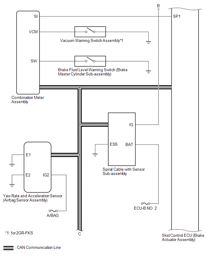
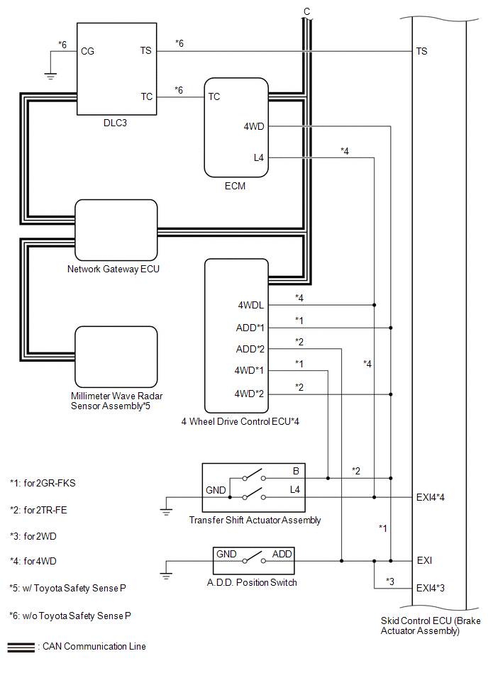
SYSTEM DIAGRAM
|
Transmitting ECU (Transmitter) |
Receiving ECU |
Signal |
Communication Method |
|---|---|---|---|
|
Skid control ECU (Brake actuator assembly) |
Steering angle sensor (Spiral cable with sensor sub-assembly) |
Steering angle sensor request signal |
CAN communication system |
|
Steering angle sensor (Spiral cable with sensor sub-assembly) |
Skid control ECU (Brake actuator assembly) |
Steering angle sensor signal |
CAN communication system |
|
Skid control ECU (Brake actuator assembly) |
Yaw rate and acceleration sensor (Airbag sensor assembly) |
Yaw rate and acceleration request signal |
CAN communication system |
|
Yaw rate and acceleration sensor (Airbag sensor assembly) |
Skid control ECU (Brake actuator assembly) |
Yaw rate and acceleration signal |
CAN communication system |
|
Skid control ECU (Brake actuator assembly) |
ECM |
|
CAN communication system |
|
ECM |
Skid control ECU (Brake actuator assembly) |
|
CAN communication system |
|
Skid control ECU (Brake actuator assembly) |
Combination meter assembly |
|
CAN communication system |
|
Wheel speed signal |
Serial communication |
||
|
4 wheel drive control ECU*3 |
Skid control ECU (Brake actuator assembly) |
|
CAN communication system |
- *1: for 4WD
- *2: w/ Rear Differential Lock
- *3: for 4WD or with Rear Differential Lock
- *4: w/o Toyota Safety Sense P
 System Description
SYSTEM DESCRIPTION
1. FUNCTION DESCRIPTION
(a) ABS (Anti-lock Brake System)
(1) The ABS helps prevent the wheels from locking when the brakes are applied
firmly or when braking on a slippery surf ...
 Check For Intermittent Problems
CHECK FOR INTERMITTENT PROBLEMS
1. CHECK FOR INTERMITTENT PROBLEMS
HINT:
A momentary interruption (open circuit) in the connectors and/or wire harnesses
between the sensors and ECUs can be detect ...
Other materials:
Operation Check
OPERATION CHECK
1. CHECK POWER DOOR LOCK OPERATION
NOTICE:
The operation check below is based on the non-customized initial condition of
the vehicle.
(a) Check basic functions.
(1) Check that all doors lock when the lock side of the door control switch is
pressed.
(2) Check that all doors ...
System Diagram
SYSTEM DIAGRAM
Communication Table
Sender
Receiver
Signal
Line
Main Body ECU
(Multiplex Network Body ECU)
Clearance Warning ECU Assembly
Destination information signal
CAN Communication Line
...
Stereo Component Amplifier Power Source Circuit
DESCRIPTION
This circuit provides power to the stereo component amplifier assembly.
WIRING DIAGRAM
CAUTION / NOTICE / HINT
Inspect the fuses for circuits related to this system before performing the following
inspection procedure.
PROCEDURE
1.
CHECK HARNESS AND CONNE ...
