Toyota Tacoma (2015-2018) Service Manual: Reassembly
REASSEMBLY
PROCEDURE
1. INSTALL RADIATOR GRILLE MOULDING
|
(a) Engage the 8 claws to install the radiator grille moulding. |
|
.png)
(b) Install the 8 screws.
2. INSTALL NO. 1 RADIATOR GRILLE GARNISH
(a) for Type A and Type B:
|
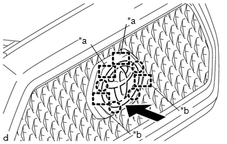
(1) Engage the 2 guides and 4 claws and 2 pins as shown in the illustration. |
|
|
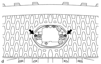
(2) Install the No. 1 radiator grille garnish with 2 new spring nuts. |
|
(b) for Type C:
|
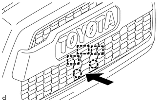
(1) Engage the 3 guides and 2 claws as shown in the illustration. |
|
|
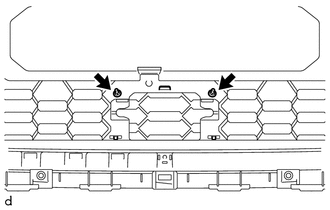
(2) Install the No. 1 radiator grille garnish with 2 new spring nuts. |
|
3. INSTALL MILLIMETER WAVE RADAR SENSOR ASSEMBLY (w/ Toyota Safety Sense P)
Click here .gif)
4. INSTALL MILLIMETER WAVE RADAR WIRE (w/ Toyota Safety Sense P)
Click here
 Installation
INSTALLATION
PROCEDURE
1. INSTALL RADIATOR GRILLE
(a) Engage the 10 guides to install the radiator grille.
(b) Install the 2 clips.
(c) Install the 2 screws.
(d) Remove the protective tape.
(e) ...
 Rear Body Side Panel Protector
Components
COMPONENTS
ILLUSTRATION
ILLUSTRATION
Installation
INSTALLATION
CAUTION / NOTICE / HINT
HINT:
Use the same procedure for the RH side and LH side.
The following pr ...
Other materials:
FCM Destination Information Unmatched (C1AA1)
DESCRIPTION
When the forward recognition camera is replaced with a new one, the new forward
recognition camera attempts to store country specification information received
from the main body ECU (multiplex network body ECU) and ECM. If the country specification
information stored in the forwa ...
Brake System (P157800)
DESCRIPTION
This DTC is output when the VSC system has a problem. Check the VSC system when
this DTC is output.
DTC No.
DTC Detection Condition
Trouble Area
MIL
Note
P157800
Diagnosis Condition:
Cr ...
Adjustment
ADJUSTMENT
PROCEDURE
1. PREPARE VEHICLE FOR HEADLIGHT AIM ADJUSTMENT
(a) Prepare the vehicle:
Ensure that there is no damage or deformation to the body around the
headlights.
Fill the fuel tank.
Make sure that the oil is filled to the specified level.
Make sure that the co ...
