Toyota Tacoma (2015-2018) Service Manual: Radio Antenna Cord
Components
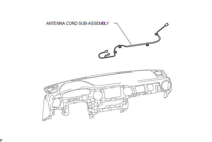
COMPONENTS
ILLUSTRATION
Removal
REMOVAL
PROCEDURE
1. REMOVE INSTRUMENT PANEL SUB-ASSEMBLY
(See page .gif) )
)
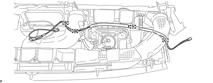
2. REMOVE ANTENNA CORD SUB-ASSEMBLY
(a) Disengage the 4 clamps to remove the antenna cord sub-assembly.
Installation
INSTALLATION
PROCEDURE
1. INSTALL ANTENNA CORD SUB-ASSEMBLY
(a) Engage the 4 clamps to install the antenna cord sub-assembly.
2. INSTALL INSTRUMENT PANEL SUB-ASSEMBLY
(See page .gif) )
)
 Radio Antenna
Components
COMPONENTS
ILLUSTRATION
Removal
REMOVAL
PROCEDURE
1. REMOVE ROOF HEADLINING ASSEMBLY (for Double Cab)
(See page )
2. REMOVE ROOF HEADLINING ASSEMBLY (for Access Cab)
(See p ...
 Radio Receiver
Components
COMPONENTS
ILLUSTRATION
ILLUSTRATION
Removal
REMOVAL
PROCEDURE
1. REMOVE INSTRUMENT CLUSTER CENTER FINISH PANEL SUB-ASSEMBLY
(See page )
2. REMOVE RADIO AND DISPLAY RECEI ...
Other materials:
Security Indicator Light Does not Blink
DESCRIPTION
The certification ECU (smart key ECU assembly) blinks the security indicator
light when the immobiliser is set (engine switch off, or driver door is
opened and closed with engine switch on (IG)).
The certification ECU (smart key ECU assembly) receive the security
...
Removal
REMOVAL
PROCEDURE
1. PRECAUTION
CAUTION:
Be sure to read Precaution thoroughly before servicing (See page
).
NOTICE:
After turning the ignition switch off, waiting time may be required before disconnecting
the cable from the negative (-) battery terminal. Therefore, make sure to read the
...
Pre-collision System Warning Buzzer
Components
COMPONENTS
ILLUSTRATION
*1
SKID CONTROL BUZZER
-
-
Inspection
INSPECTION
PROCEDURE
1. INSPECT SKID CONTROL BUZZER
(a) Make sure that there is no looseness in the locking part and connecting
part of the conne ...
