Toyota Tacoma (2015-2018) Service Manual: Radio Antenna
Components
COMPONENTS
ILLUSTRATION
Removal
REMOVAL
PROCEDURE
1. REMOVE ROOF HEADLINING ASSEMBLY (for Double Cab)
(See page .gif) )
)
2. REMOVE ROOF HEADLINING ASSEMBLY (for Access Cab)
(See page )
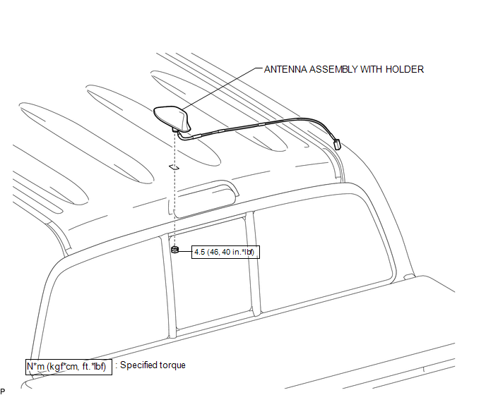
3. REMOVE ANTENNA ASSEMBLY WITH HOLDER
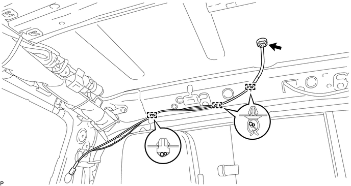
(a) Disengage the 3 clamps.
(b) Remove the nut.
|
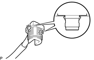
(c) Disengage the 2 claws to remove the antenna assembly with holder. |
|
Installation
INSTALLATION
PROCEDURE
1. INSTALL ANTENNA ASSEMBLY WITH HOLDER
(a) Engage the 2 claws to install the antenna assembly with holder.
(b) Install the nut.
Torque:
4.5 N·m {46 kgf·cm, 40 in·lbf}
(c) Engage the 3 clamps.
2. INSTALL ROOF HEADLINING ASSEMBLY (for Double Cab)
(See page .gif) )
)
3. INSTALL ROOF HEADLINING ASSEMBLY (for Access Cab)
(See page )
 Noise Filter(for 2tr-fe)
Components
COMPONENTS
ILLUSTRATION
Removal
REMOVAL
PROCEDURE
1. DISCONNECT CABLE FROM NEGATIVE BATTERY TERMINAL
2. REMOVE AIR CLEANER ASSEMBLY
(See page )
3. REMOVE RADIO SETTING COND ...
 Radio Antenna Cord
Components
COMPONENTS
ILLUSTRATION
Removal
REMOVAL
PROCEDURE
1. REMOVE INSTRUMENT PANEL SUB-ASSEMBLY
(See page )
2. REMOVE ANTENNA CORD SUB-ASSEMBLY
(a) Disengage the 4 clamps to remo ...
Other materials:
Side Turn Signal Light Assembly
Components
COMPONENTS
ILLUSTRATION
Removal
REMOVAL
CAUTION / NOTICE / HINT
HINT:
Use the same procedure for both the RH and LH sides.
The procedure described below is for the LH side.
PROCEDURE
1. REMOVE OUTER REAR VIEW MIRROR ASSEMBLY
(See page )
2. REMOVE OUTER ...
Dtc Check / Clear
DTC CHECK / CLEAR
1. CHECK FOR DTC
HINT:
When using the Techstream with the engine switch off, connect the Techstream
to the DLC3 and turn a courtesy light switch on and off at intervals of 1.5 seconds
or less until communication between the Techstream and the vehicle begins. Then
select th ...
Installation
INSTALLATION
CAUTION / NOTICE / HINT
HINT:
Use the same procedure for the RH and LH sides.
The procedure described below is for the LH side.
PROCEDURE
1. REPAIR INSTRUCTION
(a) Clean the vehicle body surface.
(1) Using a heat light, heat the vehicle body surface.
Heating Te ...
