Toyota Tacoma (2015-2018) Service Manual: Radio Receiver
Components
COMPONENTS
ILLUSTRATION
ILLUSTRATION
Removal
REMOVAL
PROCEDURE
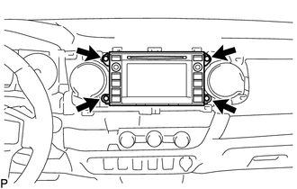
1. REMOVE INSTRUMENT CLUSTER CENTER FINISH PANEL SUB-ASSEMBLY
(See page .gif) )
)
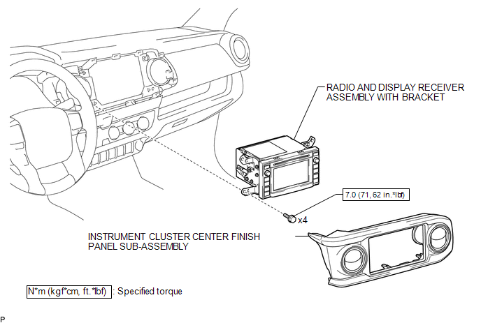
2. REMOVE RADIO AND DISPLAY RECEIVER ASSEMBLY WITH BRACKET
|
(a) Remove the 4 bolts. |
|
(b) Disconnect the connectors to remove the radio and display receiver assembly with bracket.
3. REMOVE NO. 1 NAVIGATION WIRE (w/ Satellite Radio)
(See page )
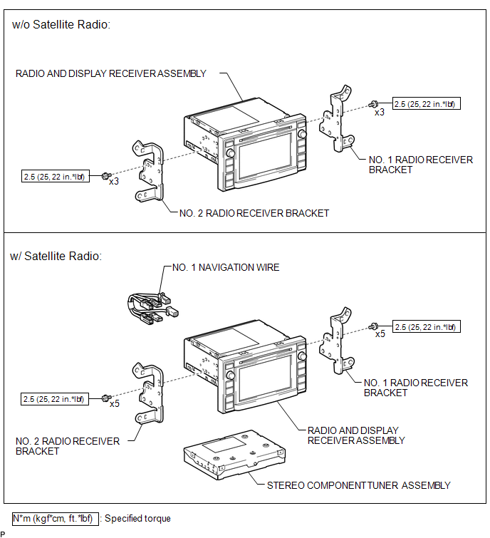
4. REMOVE NO. 1 RADIO RECEIVER BRACKET
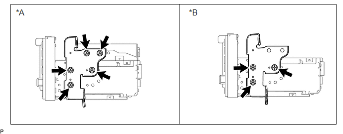
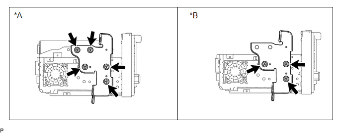 Text in Illustration
|
*A |
w/ Satellite Radio |
*B |
w/o Satellite Radio |
(a) w/ Satellite Radio:
Remove the 5 bolts and No. 1 radio receiver bracket.
(b) w/o Satellite Radio:
Remove the 3 bolts and No. 1 radio receiver bracket.
5. REMOVE NO. 2 RADIO RECEIVER BRACKET
 Text in Illustration
|
*A |
w/ Satellite Radio |
*B |
w/o Satellite Radio |
(a) w/ Satellite Radio:
Remove the 5 bolts and No. 2 radio receiver bracket.
(b) w/o Satellite Radio:
Remove the 3 bolts and No. 2 radio receiver bracket.
6. REMOVE STEREO COMPONENT TUNER ASSEMBLY (w/ Satellite Radio)
(See page )
Installation
INSTALLATION
PROCEDURE
1. INSTALL STEREO COMPONENT TUNER ASSEMBLY (w/ Satellite Radio)
(See page .gif) )
)
2. INSTALL NO. 2 RADIO RECEIVER BRACKET
(a) w/ Satellite Radio:
Install the No. 2 radio receiver bracket with the 5 bolts.
Torque:
2.5 N·m {25 kgf·cm, 22 in·lbf}
(b) w/o Satellite Radio:
Install the No. 2 radio receiver bracket with the 3 bolts.
Torque:
2.5 N·m {25 kgf·cm, 22 in·lbf}
3. INSTALL NO. 1 RADIO RECEIVER BRACKET
(a) w/ Satellite Radio:
Install the No. 1 radio receiver bracket with the 5 bolts.
Torque:
2.5 N·m {25 kgf·cm, 22 in·lbf}
(b) w/o Satellite Radio:
Install the No. 1 radio receiver bracket with the 3 bolts.
Torque:
2.5 N·m {25 kgf·cm, 22 in·lbf}
4. INSTALL NO. 1 NAVIGATION WIRE (w/ Satellite Radio)
(See page )
5. INSTALL RADIO AND DISPLAY RECEIVER ASSEMBLY WITH BRACKET
(a) Connect the connectors.
(b) Install the radio and display receiver assembly with bracket with the 4 bolts.
Torque:
7.0 N·m {71 kgf·cm, 62 in·lbf}
6. INSTALL INSTRUMENT CLUSTER CENTER FINISH PANEL SUB-ASSEMBLY
(See page )
 Radio Antenna Cord
Components
COMPONENTS
ILLUSTRATION
Removal
REMOVAL
PROCEDURE
1. REMOVE INSTRUMENT PANEL SUB-ASSEMBLY
(See page )
2. REMOVE ANTENNA CORD SUB-ASSEMBLY
(a) Disengage the 4 clamps to remo ...

Other materials:
How To Proceed With Troubleshooting
CAUTION / NOTICE / HINT
HINT:
Use the following procedure to troubleshoot the power window control
system.
*: Use the Techstream.
PROCEDURE
1.
VEHICLE BROUGHT TO WORKSHOP
NEXT
...
Slip Indicator Light Remains ON
DESCRIPTION
The slip indicator light blinks during VSC or TRAC and AUTO LSD operation. When
the system fails, the slip indicator light comes on to warn the driver.
WIRING DIAGRAM
CAUTION / NOTICE / HINT
NOTICE:
When replacing the skid control ECU (master cylinder solenoid), perform ...
ECM Communication Circuit Malfunction (C1203)
DESCRIPTION
The circuit is used to send TRAC and VSC control information from the skid control
ECU (brake actuator assembly) to the ECM, and engine control information from the
ECM to the skid control ECU (brake actuator assembly) through the CAN communication
system.
for 4WD or w/ Rear Diff ...
