Toyota Tacoma (2015-2018) Service Manual: Pcv Valve
Components
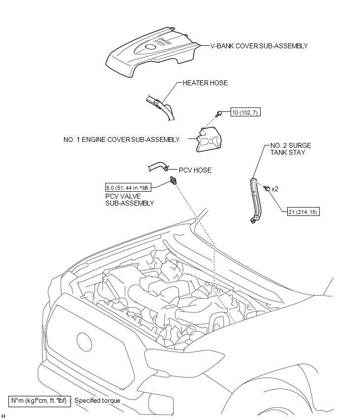
COMPONENTS
ILLUSTRATION
Inspection
INSPECTION
PROCEDURE
1. INSPECT PCV VALVE SUB-ASSEMBLY
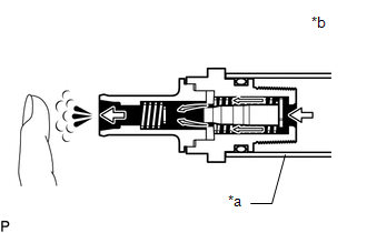
(a) Install a clean hose to the PCV valve sub-assembly.
(b) Check the PCV valve sub-assembly operation.
(1) Blow air into the cylinder head cover sub-assembly LH side and check that air passes through easily. If the result is not as specified, replace the PCV valve sub-assembly.
 Text in Illustration
|
*a |
Clean Hose |
|
*b |
Cylinder Head Cover Sub-assembly LH Side |
.png) |
Air |
If the result is not as specified, replace the PCV valve sub-assembly.
CAUTION:
Do not suck air through the valve. Petroleum substances inside the valve are hazardous to your health.
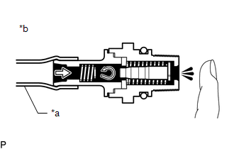
(2) Blow air into the intake air surge tank side and check that air passes through with difficulty.
 Text in Illustration
|
*a |
Clean Hose |
|
*b |
Intake Air Surge Tank Side |
|
|
Air |
If the result is not as specified, replace the PCV valve sub-assembly.
(c) Remove the clean hose from the PCV valve sub-assembly.
Removal
REMOVAL
PROCEDURE
1. REMOVE V-BANK COVER SUB-ASSEMBLY
.gif)
2. REMOVE NO. 2 SURGE TANK STAY
3. DISCONNECT HEATER HOSE
|
(a) Disengage the clamp and disconnect the heater hose. |
|
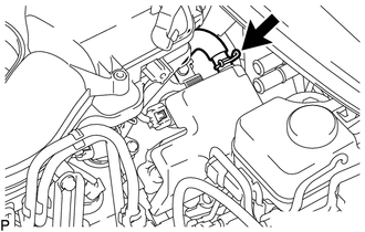
4. DISCONNECT PCV HOSE
|
(a) Slide the clip and disconnect the PCV hose from the cylinder head cover sub-assembly LH. |
|
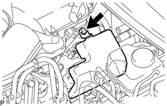
5. REMOVE NO. 1 ENGINE COVER SUB-ASSEMBLY
|
(a) Remove the bolt and No. 1 engine cover sub-assembly from the cylinder head cover sub-assembly LH. |
|
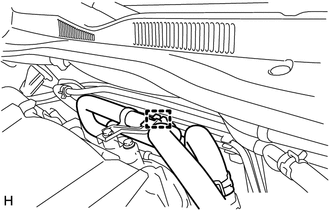
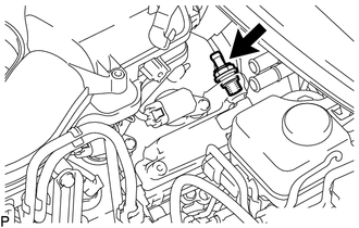
6. REMOVE PCV VALVE SUB-ASSEMBLY
|
(a) Remove the PCV valve sub-assembly from the cylinder head cover sub-assembly LH. |
|
Installation
INSTALLATION
PROCEDURE
1. INSTALL PCV VALVE SUB-ASSEMBLY
(a) Apply a light coat of engine oil to the O-ring.
(b) Install the PCV valve sub-assembly to the cylinder head cover sub-assembly LH.
Torque:
5.0 N·m {51 kgf·cm, 44 in·lbf}
NOTICE:
When reusing the PCV valve sub-assembly, inspect the O-ring.
2. INSTALL NO. 1 ENGINE COVER SUB-ASSEMBLY
(a) Install the No. 1 engine cover sub-assembly with the bolt to the cylinder head cover sub-assembly LH.
Torque:
10 N·m {102 kgf·cm, 7 ft·lbf}
3. CONNECT PCV HOSE
(a) Connect the PCV hose to the cylinder head cover sub-assembly LH, and slide the clip to secure the hose.
4. CONNECT HEATER HOSE
(a) Engage the clamp and connect the heater hose.
5. INSTALL NO. 2 SURGE TANK STAY
.gif)
6. INSTALL V-BANK COVER SUB-ASSEMBLY
 Fuel Tank Cap
Inspection
INSPECTION
PROCEDURE
1. INSPECT FUEL TANK CAP ASSEMBLY
(a) Check the appearance of the fuel tank cap assembly.
(1) Check that there is no deformation or damage to the fuel tank cap a ...
 Purge Valve
Components
COMPONENTS
ILLUSTRATION
Inspection
INSPECTION
PROCEDURE
1. INSPECT PURGE VSV
(a) Measure the resistance according to the value(s) in the table below.
Text in Illu ...
Other materials:
Components
COMPONENTS
ILLUSTRATION
*A
for Type A
*B
for Type B
*C
for Type C
-
-
*1
MILLIMETER WAVE RADAR SENSOR ASSEMBLY
*2
MILLIMETER WAVE RADAR WIRE
...
Off-road precautions (4WD models and PreRunner)
This vehicle has higher ground clearance and narrower tread in relation to
the height of its center of gravity to make it capable of performing in a wide variety
of off-road applications.
Off-road vehicle feature
● Specific design characteristics give it a higher center of gravity than o ...
Removal
REMOVAL
PROCEDURE
1. REMOVE MANUAL TRANSMISSION ASSEMBLY
(See page )
2. REMOVE CLUTCH RELEASE FORK SUB-ASSEMBLY
(a) Remove the clutch release fork sub-assembly with the clutch release
bearing assembly from the manual transmission assembly.
...
